1968 Ford XL Four Wheel Disc Conversion with ABS, Line Lock and Traction Control - part 1
2023, November 14
Hello Everyone,
I'm intermixing my time on restoring the 1966 Ford Galaxie. Now back to this 1968 Ford XL as well as my old convertible whose make we shall not speak off (Chevrolet), but the Chevy did come with a factory big block so we have to cut it some slack.
Right, back on topic. My '68 already came with power front disc brakes, but as (1) rotors are expensive, (2) the front hoses are hard to find as well as being expensive, (3) cutting the rotors involves dealing with greasy hub bearings and (4) there are no existing Anti-loc or traction control. I aint have'n it!
My plan is to adapt this old Ford XL to the newer panther chassis (Crown Victoria, Grand Marquis, Lincoln Towncar) 4 wheel disc brakes with the modulator for traction control and Antiloc. I'll be adding this to our 1966 Fords as well.
Before I get into the thick of it, I should explain I'm probably not going to use the factory control module for the ABS/TC. Because I want to be able to turn it either on or off and also add a feature for line locking the front brakes so I can, of course, act like I'm 12 for some rear tyre smoking fun. But I'll probably grab a module from the recycle yard and see if I can read the existing firmware in them for the basic algorithms which will save me some time designing my own. I mean why reinvent the wheel when you don't have to.
So I've started on the front brake conversion yesterday:
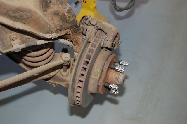
1 - Original factory disc brake setup (drivers side)
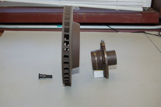
2 - Exploded assembly view of original brakes, as you can see the rotor is affixed to the backside of the wheel hub with the studs pressed through holding them together.
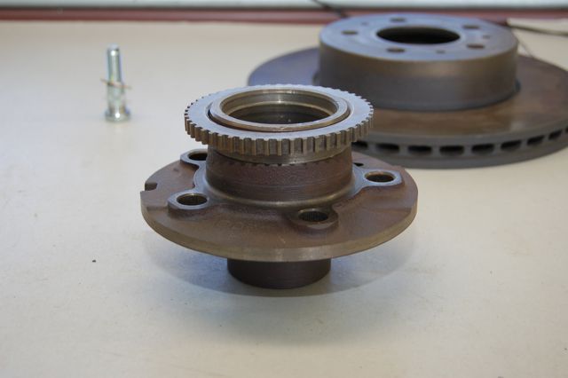
3 - My solution is to use modern panther chassis rotors, pads, calipers and the reluctor ring. I went through Dormans entire catalog of wheel studs (which they kindly provided all critical dimensions) and picked out new studs that would work the best. I added one flat AN washer to give the proper final fitment. As a result, now the rotors slide on the front of the hub and the tyre rim holds it in place, just like a newer car.

4 - I machined the hub for the reluctor ring to press on and also took about 1.3mm (~0.050") off the outside of the hub to clear the inside of the newer rotors.
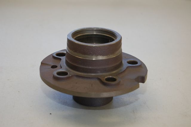
5 - A problem is that the hub suffered from "core shift" at the forge when it was casted. There's not enough material for a proper machining job. I'll need to build up the surface with a machinable weld.
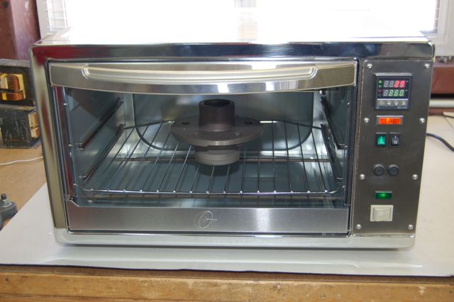
6 - So in the oven it goes to be preheated to 260˚C (500˚F), welded, then a controlled cooling to bring down the temperature 10˚C (50˚F) every hour until under the boiling point of water, then it can naturally cool by itself. This keeps the nodular cast iron from becoming brittle.
The oven is a modified, off-the-shelf electric convection I bought at Wally World (Walmart). I chucked the consumer grade electronics in the bin because they are rubbish. I made a panel housing industrial control and wrapped the inner chamber with 540˚C (~1000˚F) insulation. It now goes to 340˚C, which is also used for reflowing PCB's.
7 - Here are the welding rods I used. I set my welder to AC and used 70 amps. I had the best results at the higher currents.

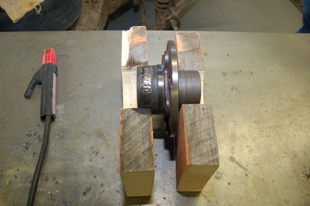
8 - My super secret welding jig, lol... It doesn't have to be mission control quality to get this job done.
9 - This is my first time using nickel alloy rod on cast iron and it didn't turn out too bad. I made a couple of passes.
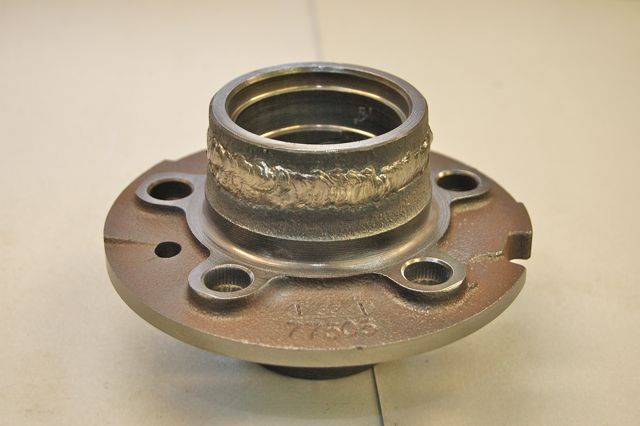
10 - There's the old hub remachined, with the studs and reluctor wheel pressed in place.
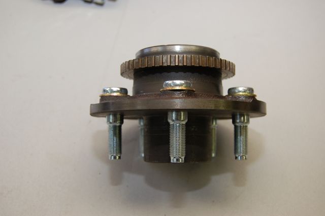
11 - Back on the car chassis with the newer rotor, the wheels stud shoulders are just right to centre the rotor on the hub. When I'm done I'll machine a centre piece for the hub to close the gap around the rotor middle hole. But it's not necessary.
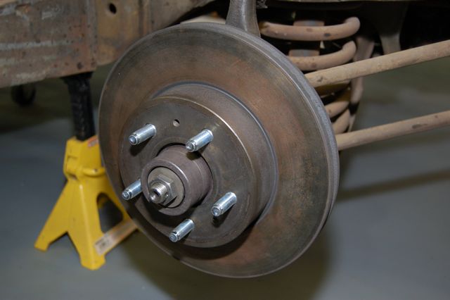
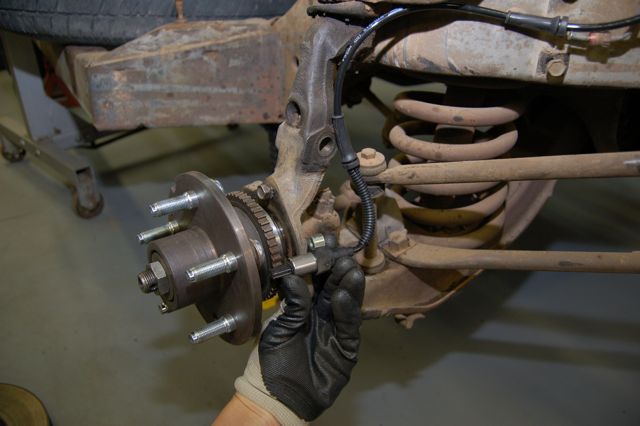
12 - The new ABS sensor will be mounted here. The next step is to dismantle this side's suspension and steering and clean everything up — I hate working on/with greasy rusty parts — then to design a bracket to hold the sensor. I'll need to do a smidgen of machining on the steering knuckle for clearance.
13 - Next, I'll make a bracket to hold the caliper bracket to the knuckle; for this I'll use Chromoly high strength steel and bracket will be all TIG welded.
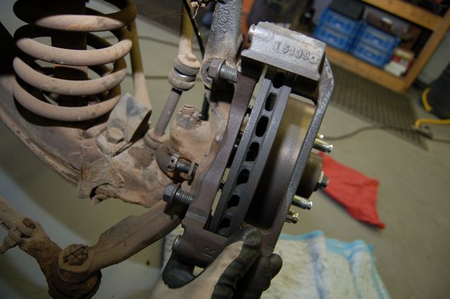
Next, I'll modify the old dust shield to fit with the newer brake components and then the fronts are done. As you've probably noticed, the front rotors will push out the tyre rims about a quarter of an inch. So when I get to the backs I'll have to, very probably, machine a spacer to bump those rims out the same amount.
Cheers,
To be continued in part 2.