Assembling a Ford 9" Third Member for a 1973 Chevy Caprice - part 2 of 2
2023, November 14
part 1 - part 2On the new gears there will be an engraved number called pinion depth or offset or some such nomenclature. Write this down. In my case it's on the pinion gear and it's 1.030".

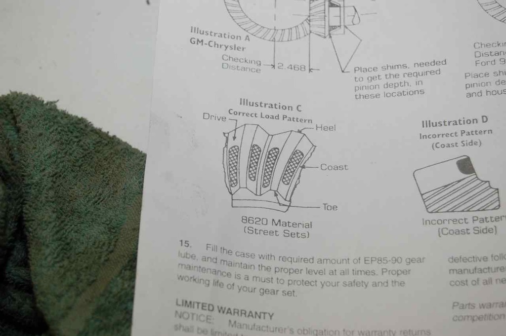
If you look at the upper right portion of the supplied instructions with the ring gear kit, this is the measurement you'll have to make and achieve with the shim assortment pack shown below.
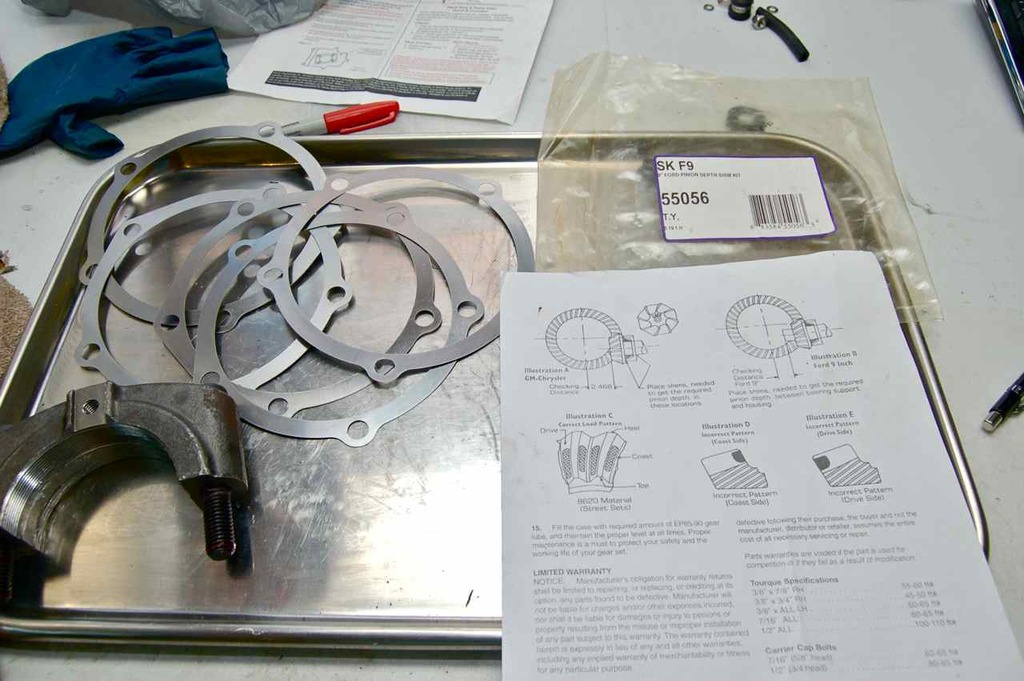
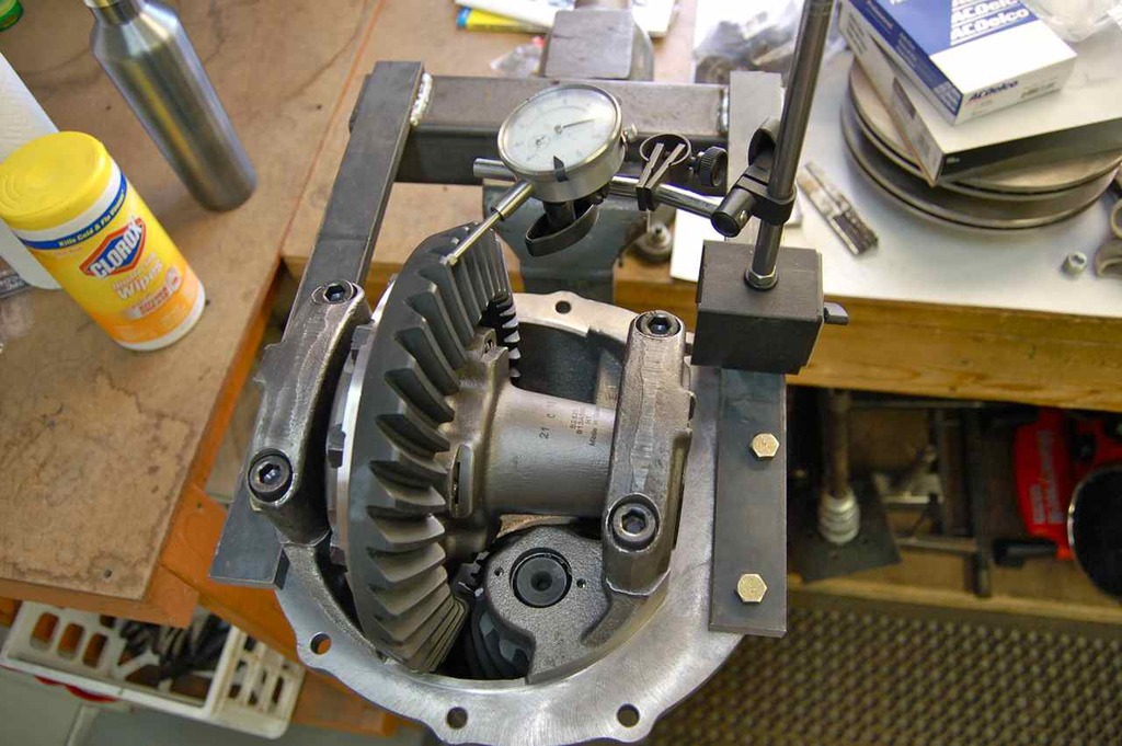
The simplest way to measure this is with:
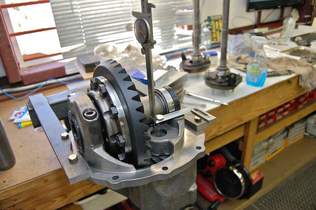
- taking one carrier bearing cap off (obviously the side closest to the pinion gear),
- use a solid piece of something (in this case it's my machinist square), and
- measure the thickness of my machinist square (or whatever you want to use), and
- measure the height of the pinion to your reference with a vernier caliper.
- Install the pinion cartridge/support piece without any shims and torque down. Leave the rubber o-ring off for now to make it easier because it'll be coming out again.
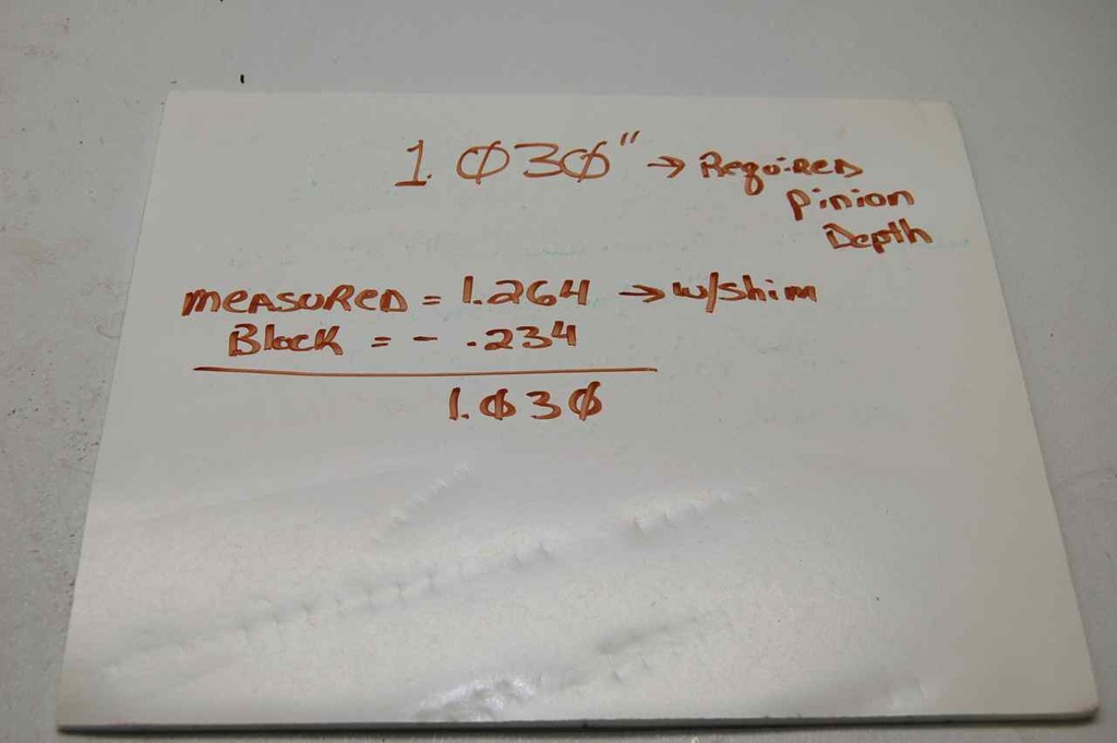
- Once you have that measurement, subtract that from the thickness of your reference piece (again in my case, my little square) and subtract this from the value of what was engraved on the pinion head.
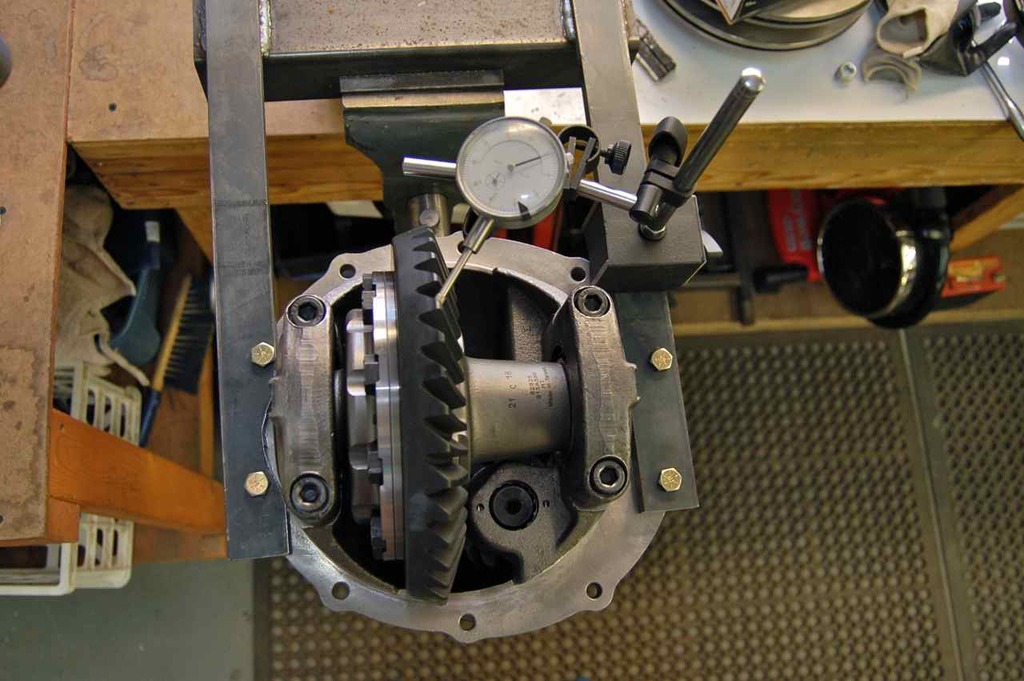
Next dig through your assortment of shims to find the closest shim that matches this difference. Install it and take another measurement. Like so.
This is my new measurement with the best fitting shim I had, the "block" in my situation is my machinist rule, the result was a perfect fit with the shim I selected.
On aftermarket gears you can skip this, but gears can be hunting, non-hunting, or semi-hunting depending on the gear ratio. This means that a non-hunting gear set will mate with the same teeth every few turns and repeats. Hunting is the teeth never really mate with the same teeth on a periodic basis and semi-hunting, well, you get the idea.
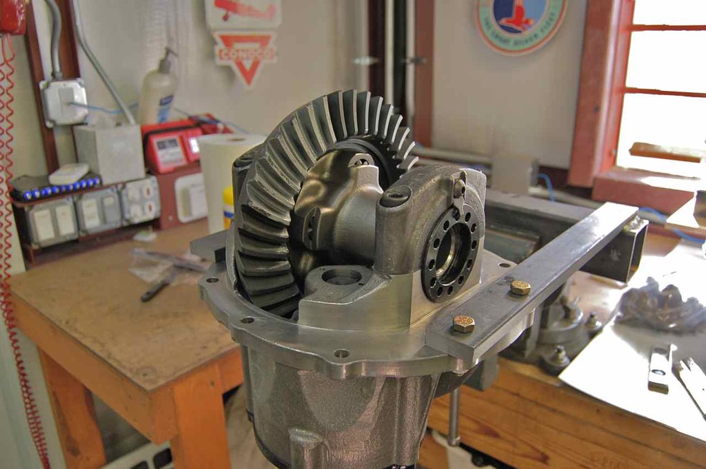
This is a 3.25:1 gear set and is non-hunting. But aftermarket gear sets seldom put the timing marks on the gears. If you look at a set of Ford gears like a 3.00:1 (non-hunting also) there are timing marks you need to line up when you install the pinion. The gears are lapped timed, if you install them with the timing marks off, you may end up with gear noise.
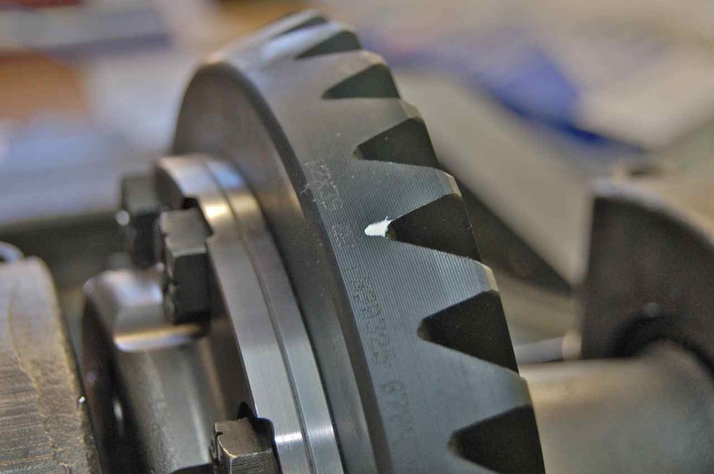
I took a chance and noticed the makers mark just happens to align in a valley between two teeth on the ring and is on the tooth crest on the pinion, I assumed these are probably the timing marks when this gear set was lapped. I marked them so I can mate them when assembling and checking the pattern.
My white paint are where the makers stampings are located. It probably makes no difference but what the heck
Once the pinion is in with the correct height and timing marks aligned (if so marked or applies to your gear set) then next is to set the ring gear lash. The instructions say 8-12 thousandths so I spit the difference and adjusted for 0.010"
Next is to check the gear pattern.
I use anti seize, since no one locally sells the gear paint/die most commonly used. A note when checking the pattern is that you have to put a load on the gears, so hang to the pinion or yoke and let your hand act as a high drag with your other hand rotating the ring gear. You need the drag to get the teeth to mate where they will with the load of the vehicle mass acting on them.
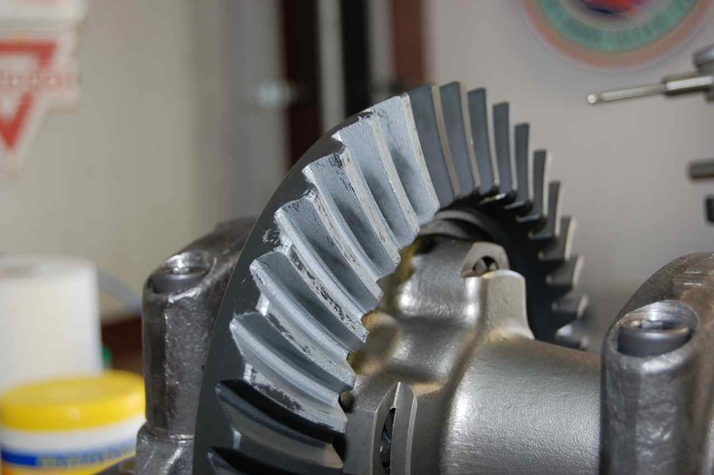

Crikey! It matches the picture in the instructions! Wow for once something aftermarket actually went together as intended. I almost fainted as I thought I would have to play with it for ages trying to get the gear pattern to match the gear vendors.
Once the gears are set, make sure there is a decent preload on the carrier bearings then torque the caps down and install the bearing nut locks; use Loctite.
There, easy peasy, and you don't need really expensive measuring tools to do this with. You can get what you need measurement tool-wise on the cheap at places like Harbor Freight and Enco.
In case you're wondering what the axle looks like somewhat assembled:
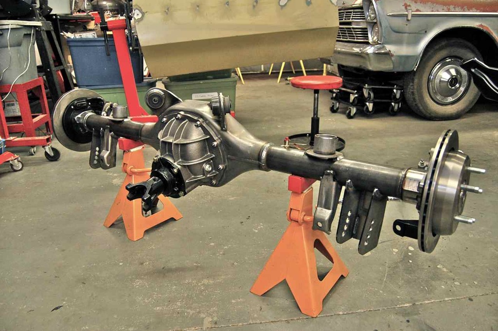
It's funny in that this is made for my 1973 Caprice Classic and uses 1996 Impala SS rear disc brakes, but this also looks like it's for a 90s Panther chassis, like my 1993 Grand Marquis. As they are triangulated 4 link suspension and the Panther rear disc brakes also use the small shoes inside the rotor hat for the parking brakes. Except the 1996 Impala SS discs are bigger and thicker as well as the calipers — a bit more heavy duty than the Panther, but then again the Impala SS was heavier than the Panthers (Crown Vic, Grand Marquis, Town Car).
Anyway, waffling over with
Hope you found this interesting.
ADDENDUM:
On setting bearing preload for the pinion, the crush sleeve is responsible for that, just follow the torque setting in the instructions either with the gear set or the galaxie service manual as they should be the same. Some people opt out of the crush sleeve and there is a kit you can buy to shim these bearings to achieve proper preload as the crush sleeve is a one time use device and must be replaced every time you take it apart where as with the shim kit once it's set up properly you can reuse over and over.
On setting the bearing preload for the carrier (diff). First the mechanism to adjust the carrier position are the end caps (the round disc with the 12 holes at either end of the bearing outer races). These screw in or out against the outer races, the outer races can slide in the housing bore accordingly. This is how to set the lash between the ring and pinion. When setting the lash, you want the bearing nuts/end caps snug (by hand) against the bearing outer races before you either take a measurement with the dial gauge or check the gear tooth pattern. As a sanity check you want to see if you can move the diff and ring gear by hand side to side, there should no end play, but it should rotate easily.
As a note, I've noticed on the galaxie FORD third member housings, with the carrier bearings caps tightened/torqued, the carrier bearing outer races move pretty easily when the bearing end caps/nuts are screwed in or out. On the aftermarket third member housing, when the caps were torqued down the bearing outer races were very tight. This can give you a false sense of bearing preload when snugging up the outer bearing nuts (round discs with 12 holes in them). You may think you have preload but the carrier may have side to side play.
Given this you want to check first that it's easy to move the carrier from side to side using the bearing nuts with the bearing caps torqued down. If not, loosen the bolts holding the bearing caps onto the third member case just enough that you can spin the bearing nuts and still move the carrier back and forth without difficulty.
Not back to setting the carrier bearing preload. The bearing nuts have a thread pitch of 16 threads per inch. There are 12 holes radially spaced on the adjuster nut face. Feel free to do the math and double check, but for every hole past the top (as a reference) you rotate the adjuster nut is 30 degrees and that works out to about 0.005" of lateral movement on the carrier.
When you snug up the outer bearing nuts to adjust your ring gear backlash, once you're happy with the backlash and gear pattern then to set bearing preload on the carrier round up to the next hole on the bearing nuts and put the locks on.
Cheers.
‹ the end ›