1994 Mercury Grand Marquis, Fixing Up a Used Panther : part 5 Reassembly
2023, November 14
part 1 - part 2 - part 3 - part 4 - part 5 - part 6 - part 7 - part 8This is the throttle body on the drivers side and you can just barely see the hose connection, trust me it's a pain to get on under all that.
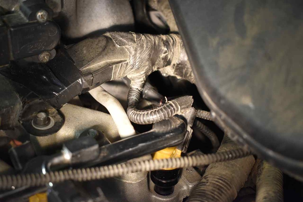
OK, that's all on, make sure all the electrical connectors are connected, the idle air control solenoid (mounted to rear intake), the EGR vacuum regulator (little black piece with the round top in near middle of picture and the EGR pressure sensor. Also installed is that manifold vacuum tube I showed earlier, connected at both ports on either side of the rear intake (another pain) and the plastic tube extension for the PCV valve.
Also the main vacuum hose that connects the pass side vacuum port on throttle body to the vacuum manifold on the firewall.
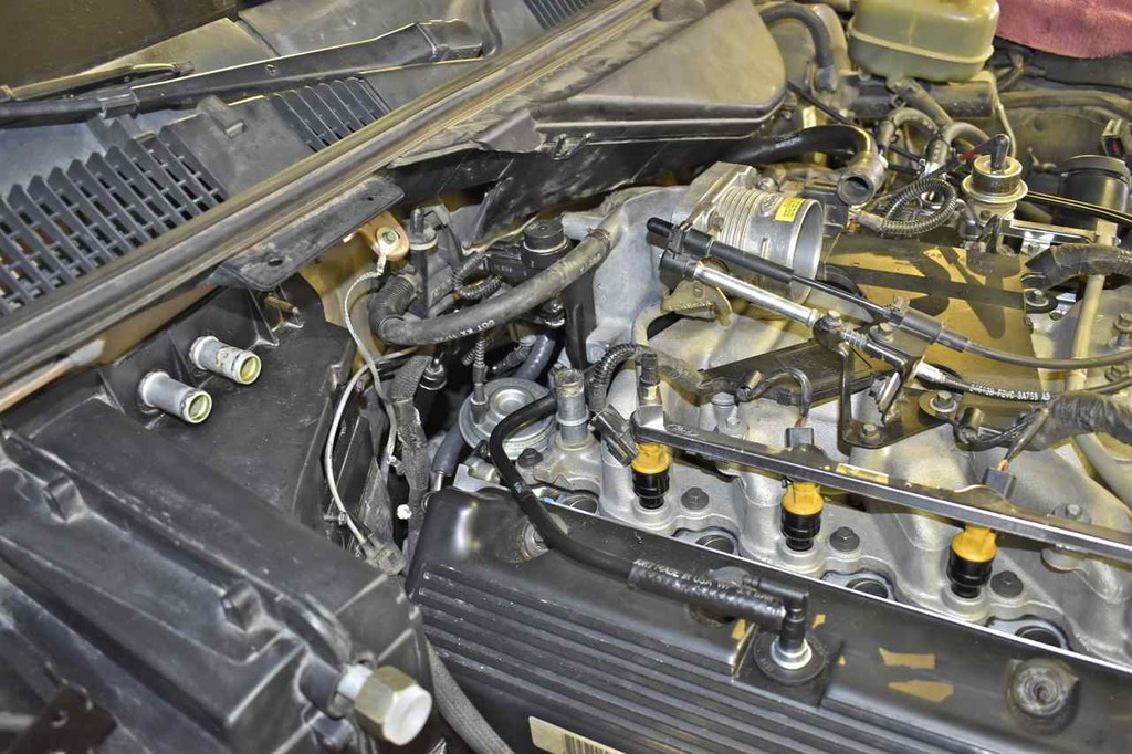
Now is the time to put that stud that holds that coolant pipe mentioned much earlier on in as no more need to work way back there.

Ground strap goes on the stud portion.

Next install the blower speed module or resistor pack if you've got the manual HVAC controls.
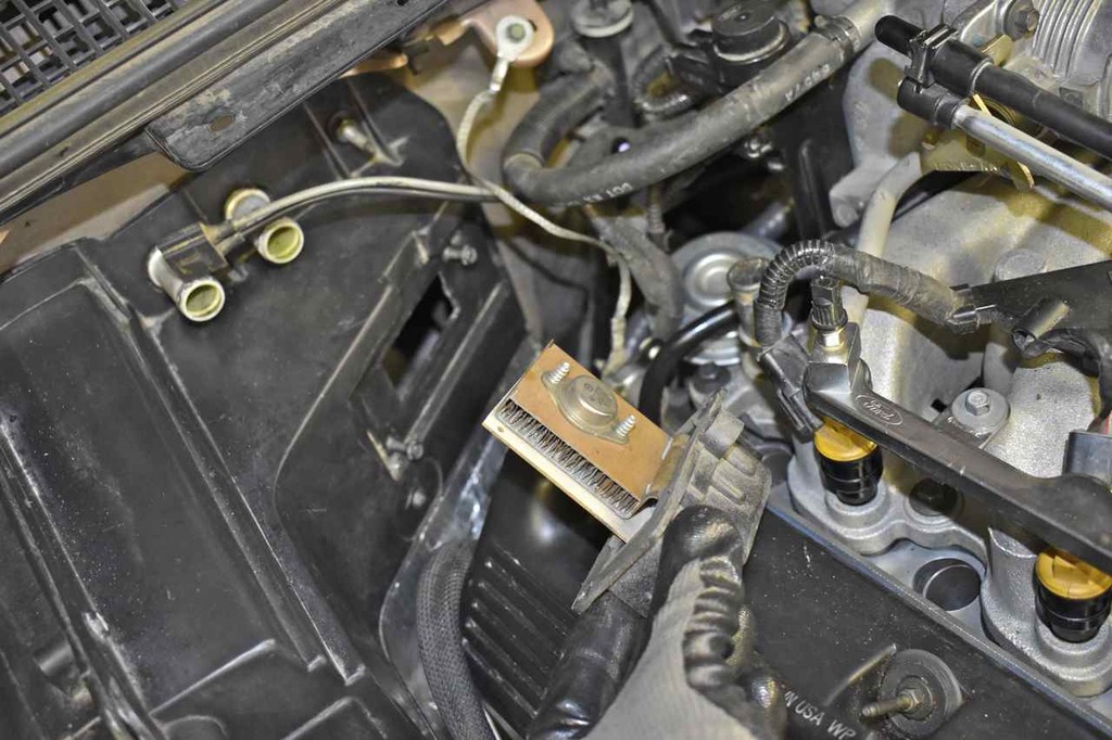
Next is the HVAC wiring harness. Secure and connect.
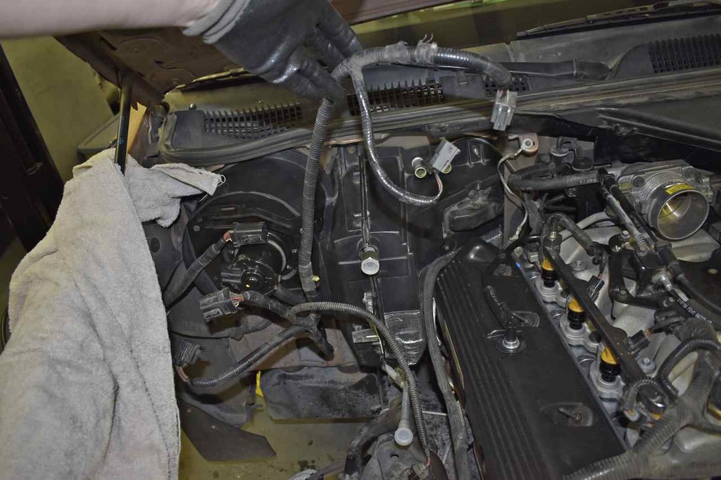
Sorry for the blurry picture.

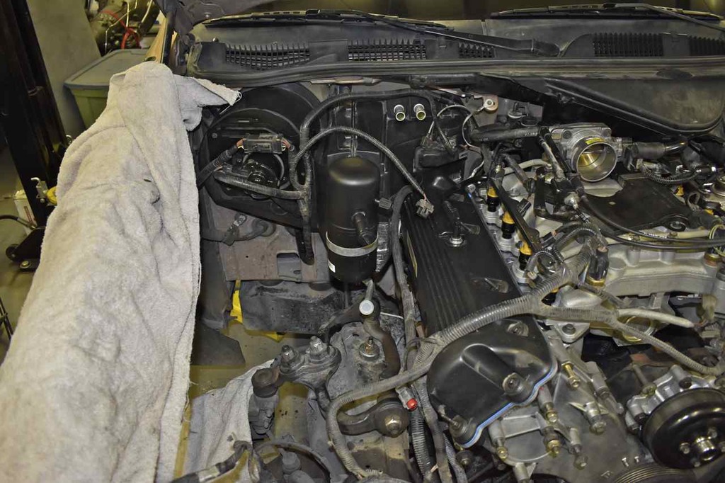
Next install the new accumulator.

New O-ring and soak it and the fitting in refrigerant oil. Since this car is R134a, use the PAG oil. As a note Harbor Freight sells the O-Ring assortment that works really well.
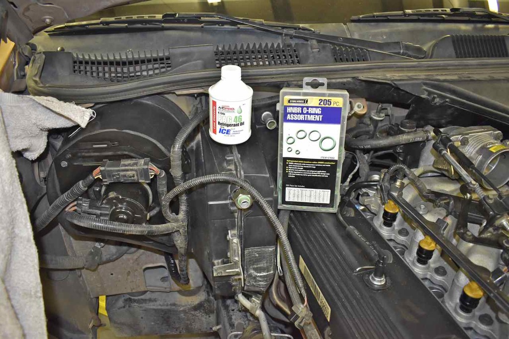
Tightened and secured with band clamp.
More of it.
Can replace the pass side inner apron, this snakes in kind of tricky, the metal ears on the right need to go above the ledge in the front.
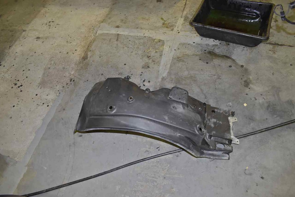
The apron will hold itself up once in. This clamp goes in.
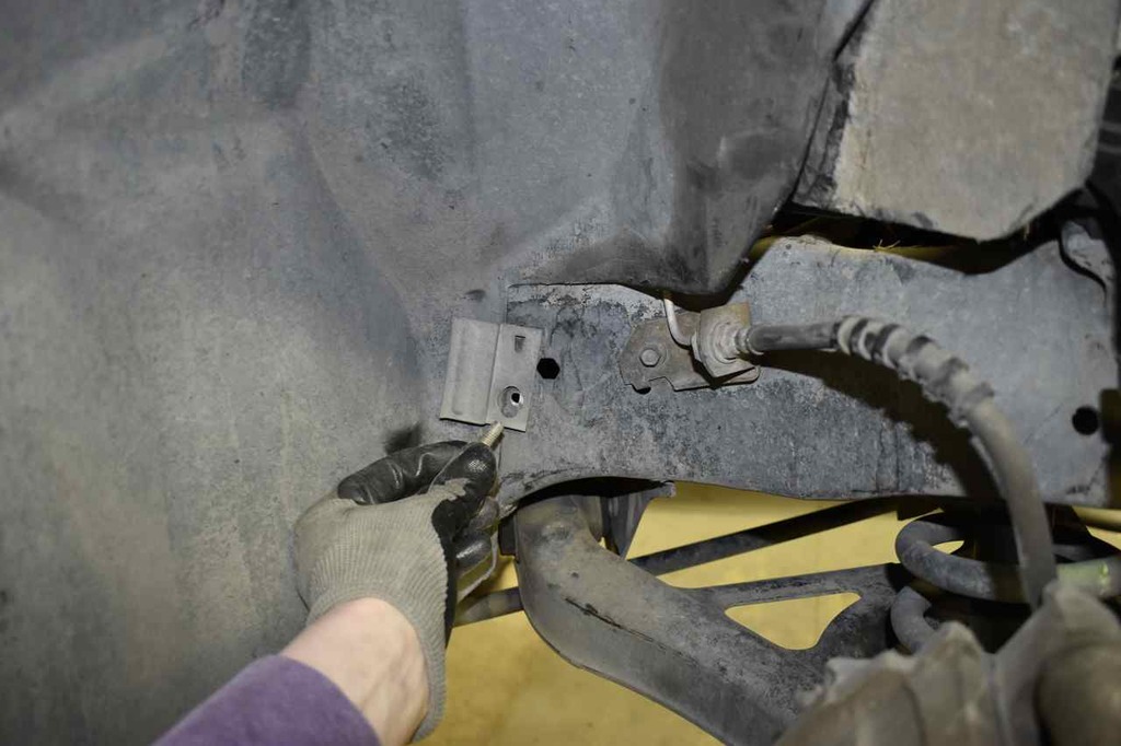
These two large fender washers go up in the top of the apron.

There is one bolt up front that goes in from the side.

These two holding the battery tray portion in.

The brace for the battery tray and that's the apron installed.
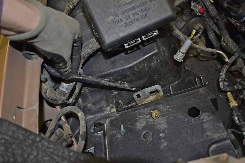
The engine bay fuse/relay block can be bolted back down.

The vapor canister hoses can be fed up through the hole in the apron. Keep track of which hose goes to the purge solenoid and which goes to the vent line.

They run up along the back side of the battery area.
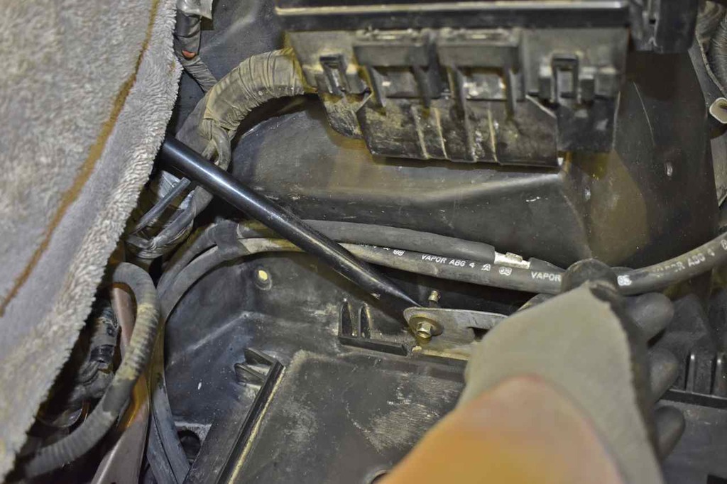
Vent hose to gas tank.

Install the purge solenoid.

Starting to look like an engine compartment now.
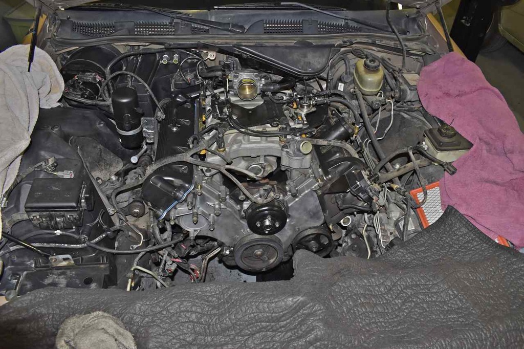
The positive battery power leads can be attached to the stud on the fuse/relay box.

Negative lead to the body bolt.
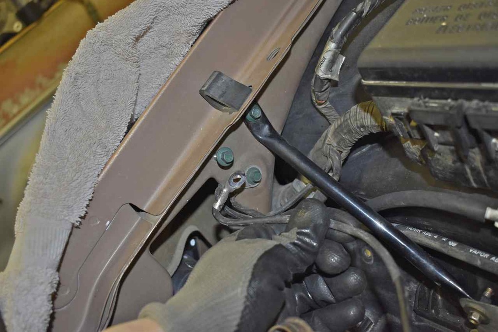
Last bit here is the splash guard.
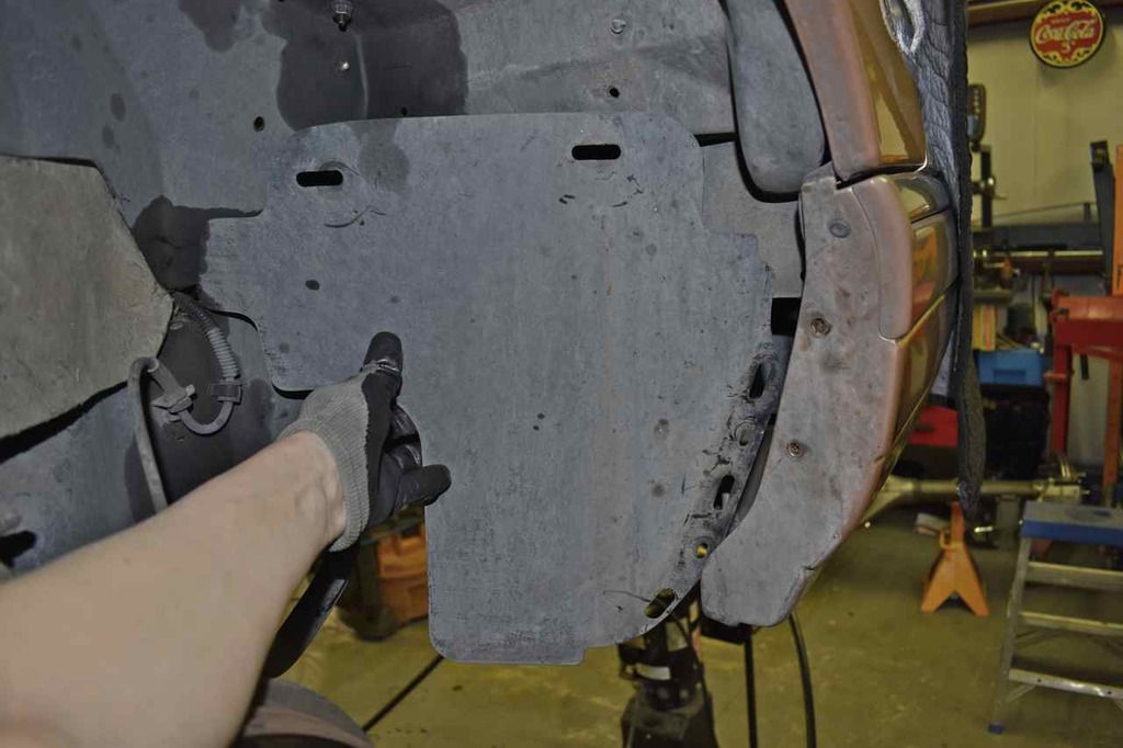
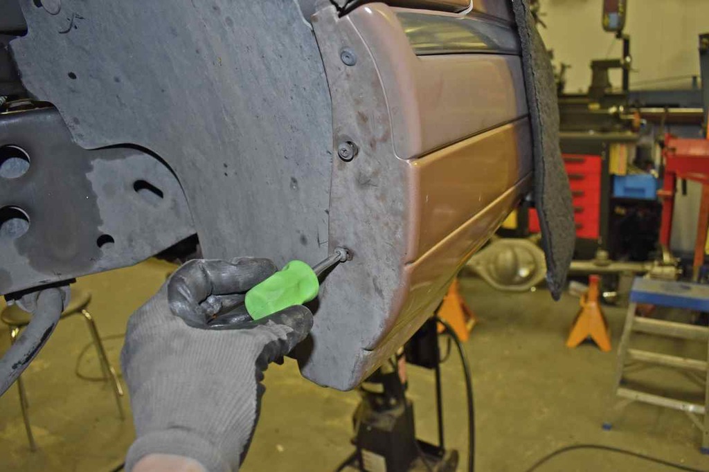
This part of the splash guard is wedged between the front wing/fender and bumper cover and has two push fasteners holding it in place. Kind of a pain to peel the bumper cover back. There are two large push fasteners that hold the top portion in.
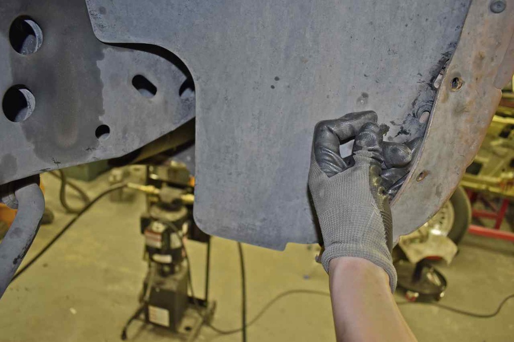
Attach the bumper cover screws to squeeze all the pieces together.
