1968 Ford AM-FM Stereo Overhaul : 01 Intro and Diagnostics - part 1 of 18
2023, November 14
1 - 2 - 3 - 4 - 5 - 6 - 7 - 8 - 9 - 10 - 11 - 12 - 13 - 14 - 15 - 16 - 17 - 18Hello,
This is going to be a very long posting when it's all finished. I realize this is probably beyond the average person, but I wanted to post to show what's involved in case anyone should really want to try this, of which I fully encourage and will gladly answer any questions.
Since this will be a long posting I should start with an overview of what this will entail. First is the rebuilding of the factory 1968 AM-FM Stereo radio for ford full size. Then I'll show what I intend to upgrade as far as the rest of the audio system for the car.
My goal for the car (1968 XL fastback) is to have everything stock looking on the inside of the car and use the original radio but upgrade the rest of the system so it sounds much much, much, did I mention much, better than the 6 watts rms it had when it left the factory.
I'll say this, the radio I chose to rebuild had a great deal wrong with it and was very time consuming and probably represents a worse case scenario.
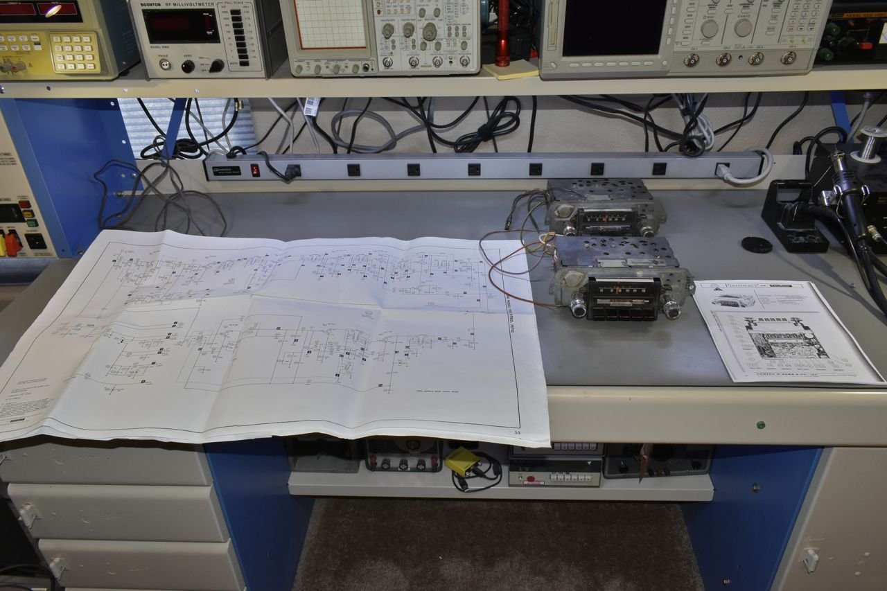
I'm starting with 2 spare radios I procured off of Fleece-Bay over the years for the 1968. To the best of my knowledge only 1968 full size fits 1968 full size and nothing else. Finding one takes time as the AM-FM radios of the 3rd gens were the second most expensive option on the cars and not very common.
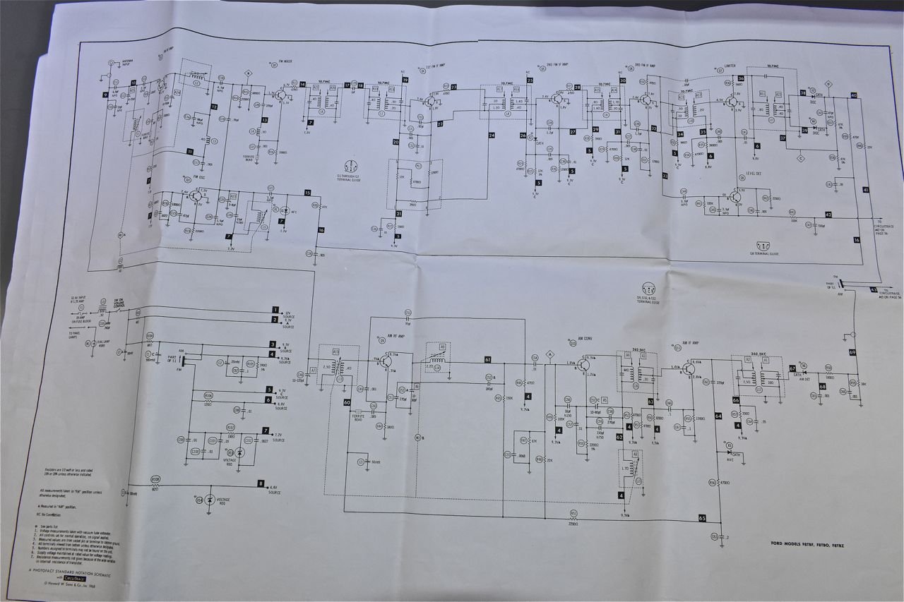
This is the schematic for the AM and FM front end as well as the power supply section.
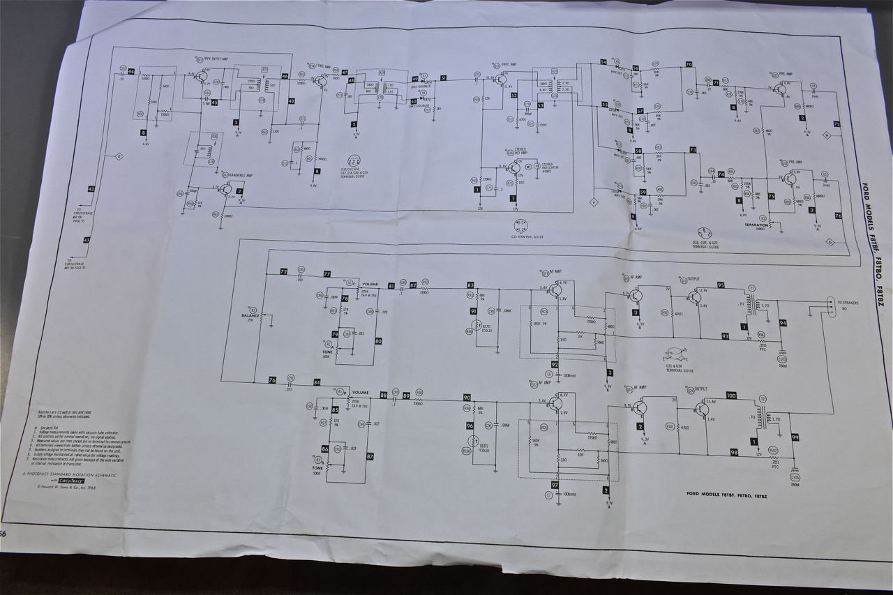
The last page of the schematic shows the stereo decoder (demultiplexer) and the L & R amplifiers, about all 3 watts per channel of them.

I chose this one of the two because it was the cleanest and no other reason.
Now for those who might have investigated repairing older electronics you may have heard to replace all the electrolytic capacitors first type of mantra going around.
I'm going to take a different approach, mostly because I want to efficiently repair the radio. With that I will power it up and make notes of what is wrong then diagnose atop of what is already likely faulty or failing capacitors as the radio will have to come mostly apart and I wish to repair as much as possible the first time around.
When I powered it up on the bench, I found AM completely dead, the volume was severely attenuated on FM to the point where it was nearly full volume on the knob to get ambient listening level out of the speakers. The left channel is crackling and the stereo lamp doesn't appear to be glowing on any FM stereo station. Oh and the manual tuning knob is just slipping and doesn't move the dial hardly at all.
So lets start with the AM portion first.
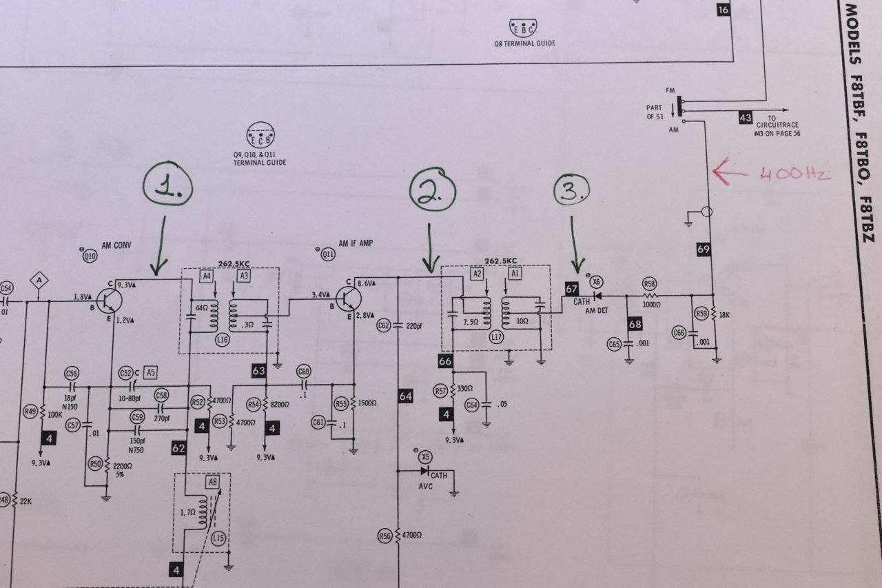
The plan is to first inject a 400 Hz tone where I have it in red ink to see if the signal is even getting to the amplifiers. If that works then divide the AM radio into 3 sections as indicated in green numbers circled and check for signal at those points.
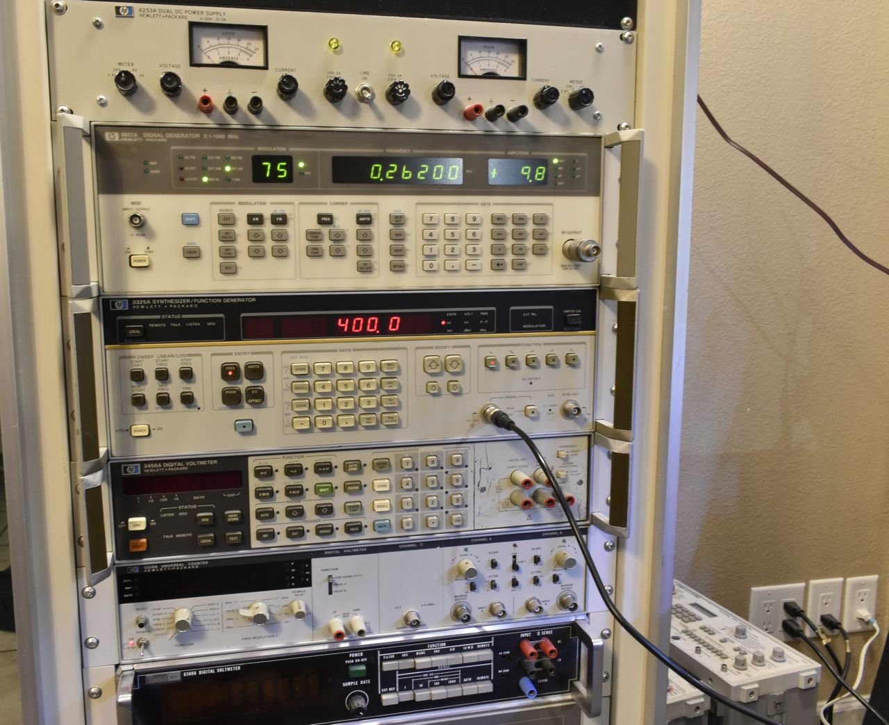
For the 400 Hz signal, any signal generator will do. If you have one of those 15 dollar kit signal generators it'll work just fine for this test, just isolate with a 0.01uF capacitor to protect your gear.
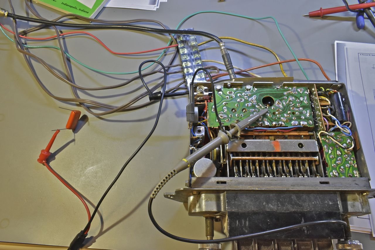
With that I do have the 400 Hz tone at the point on the schematic.

Since I know the signal is getting through at the red inked line the AM-FM selector switch is working. With that I'm going to attach an antenna again and check location one with a spectrum analyzer to check to see if the local oscillator is running. You can use a scope at this point and I would short out the antenna if you do as noise and stations coming in will muddy your local oscillator sine wave.
Using a spectrum analyzer will show the quality and amplitude of the local oscillator and with an antenna will show any station or noise at 262.5 kHz (1st IF transformer) as well.
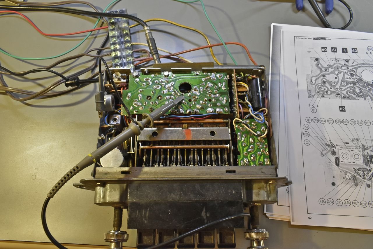
Measuring point.
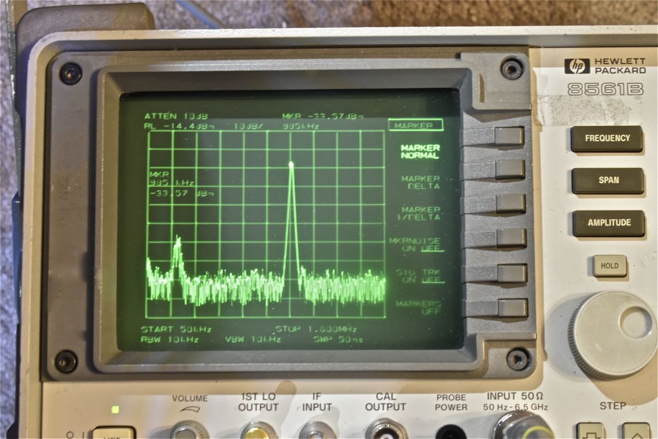
And the local oscillator is running at 985 kHz and there is a signal, be noise or a station at 262.5 kHz.
Ok, the front end of the AM radio is working.

At point 2.) I should see a greater amplitude 262.5 kHz than at point 1.) and the local oscillator will be tuned out by the first IF transformer so that's all we should see.
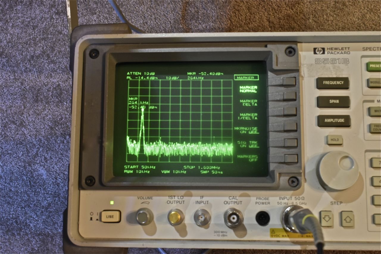
And there it is. So the first IF amplifier is working as well. This particular model spectrum analyzer has a built in AM and FM detector. If I switch on the AM demodulator, put the cursor atop the 262.5 kHz peak and turn up the volume on the spectrum analyzer I get the AM station the radio was tuned to. If I manually move the dial on the radio the AM portion is working just fine to this point.

So the AM radio works up to point 2.) next is to check point 3.)
Click here to continue to part 2