1968 Ford AM-FM Stereo Overhaul : 07 Repair - Capacitors
2023, November 14
1 - 2 - 3 - 4 - 5 - 6 - 7 - 8 - 9 - 10 - 11 - 12 - 13 - 14 - 15 - 16 - 17 - 18Radio Overhaul - Repair page 4
I need to include a few things I've forgotten to comment about. There's a condition for a certain kind of silver mica capacitor in the IF transformers that causes either a dead AM/FM band, or poor sensitivity or even poor selectivity. Sensitivity is receivers ability to receive a weak station. Selectivity is the receivers ability to focus in on one station. Too little selectivity can result in a side or adjacent station bleeding over into the station your tuned into. Too much selectivity can reduce signal bandwidth and cripple fidelity.
Back to the point. If the IF transformer has the capacitor where it's a sheet of mica plated with silver on both sides to form the capacitor and it's squeezed by contacts in the plastic base of the IF transformer this can be a problem and those need to go and be replaced with a regular silver mica encapsulated capacitor.
What happens in these IF transformers, is with time/age and use the plating of silver is so thin on the mica sheet with contaminants such as humidity and salts from the air, the current and voltage across the capacitor will start to lift the ions of the silver around the contact and it will plate the contact. When enough of them have migrated over the connection to the rest of the mica capacitor can be lost or lost intermittently. If you hear crackling on the speakers either intermittently or all the time, there's a high probability this is the cause. On vacuum tube/valve radios because of the higher voltages, you can see this type of capacitor arcing if you can look into the IF transformer either through the bottom or top with the set running. It makes one of hell of a racket on the speaker(s) when doing so.
This radio doesn't use those kinds of capacitors in the IF transformers, they are round mica ones with leads so it's not a problem.
OK that's a good segue onto electrolytic capacitor replacements.
Unfortunately, just like automotive parts, the electronic parts industry has, over the years, been plagued especially with cheap crappy parts or even counterfeit parts that look like brand name parts. These parts are junk and to be avoided.
You can give yourself the best chance to avoid counterfeit parts by ONLY buying from places like Digikey, Newark, Mouser, Allied, etc. These places do their very best to vet the parts they buy and sell. When you buy parts from radio supply houses, parts clearance houses or E-Bay or Amazon there's no guarantee and most likely those are either plain junk or counterfeit parts, which are also junk.
The primary brands of capacitors to stick to are:
1.) Panasonic 2.) Nichicon 3.) Sprague which is now owned by Vishay 4.) Illinois Capacitor
There are other brands like Kemet that are ok, but try to stick to these when possible for your application.
If you see a no name capacitor or a funny name one, just say no.
That covers the quality and supplier topic of capacitors, now lets cover the actual electrical characteristics of capacitors.
In a perfect world a capacitor has no series resistance, no parallel resistance and no series inductance. But they do. Electrolytic capacitors especially. There are all kinds of different classes of capacitors; electrolytic's, film, disc, mica, variable plate air, tantalum, etc. Here I am just going to discuss the problems with electrolytic's.
Electrolytic's are simply two rolls of conductive foil separated by an insulator soaked in a juicy and often toxic electrolyte. How's that for a sandwich
As a result of its construction, electrolytics have a service life in hours (most often from 1000 hours to 10,000 or more hours). The life depends on the temperature of which it operates and the quality of the materials used.
Here's some of the failure modes of electrolytic capacitors.
1.) The electrolytic paste-goo dries up and the capacitance goes way down, sometimes to near zero. 2.) The dielectric insulating film between the foil sheets can break down causing shorts between the two sheets of foil. 3.) The dielectric paste-goo can eat away at the foil causing the equivalent resistance of the capacitor to go way up or the dielectric breaks down causing the delayed dielectric effect to increase resistance. 4.) The dielectric paste-goo can turn caustic and eat away at the aluminum can structure then leak out of the capacitor, not only rendering the capacitor inoperative but then eat away at the traces on the PCB board around the capacitor. This happens in equipment, consumer goods and now even happening in ECU's in cars from the 80's and 90's. Fox body guys are starting to feel this with the Ford ECU's and so are the imports of that era. I bet some thought they never would have to recap their ECU's.......
I know that was a lot for a beginner, so I'll stop there and let that soak in.
The main characteristics of interest for a capacitor for uses like this are series resistance, capacitance and parallel resistance. Parallel resistance is also called leakage resistance of a capacitor and isn't so much a factor in a bi-polar transistor radio such as this, mostly because bi-polar transistors are a current device and even a slight leakage in a coupling capacitor probably will not greatly affect the Q (quiescent) point of the bias of the transistor.
However if it's a FET radio or a vacuum tube/valve radio even a slightly leaky coupling capacitor can cause high currents in FET's and even red plate tubes causing them to fail.
To further compound the complexity of capacitors, certain test equipment can test falsely to really screw with you. I'll demonstrate this and why it's just best to replace nearly all old electrolytic capacitors when in doubt.
Let's jump in.
I've removed all the electrolytic's from the radio. I'll start testing the two off the AM board.

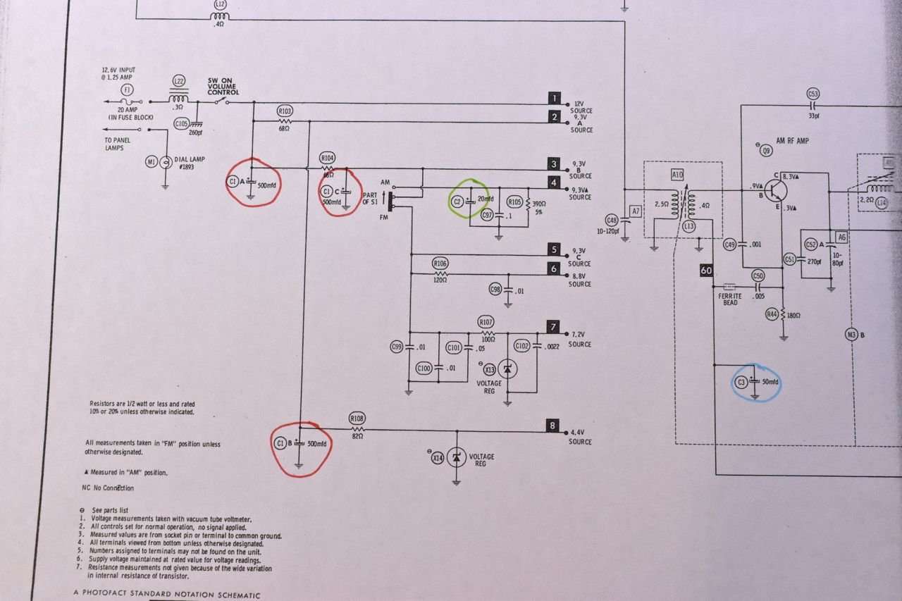
These two are circled in blue and green on the schematic.

This is the 50 uF capacitor circled in blue. This is the AVC/AGC (automatic volume control/automatic gain control) capacitor in an AM radio. If this were to open (dry out) your AM radio would squeal over most or all the band.
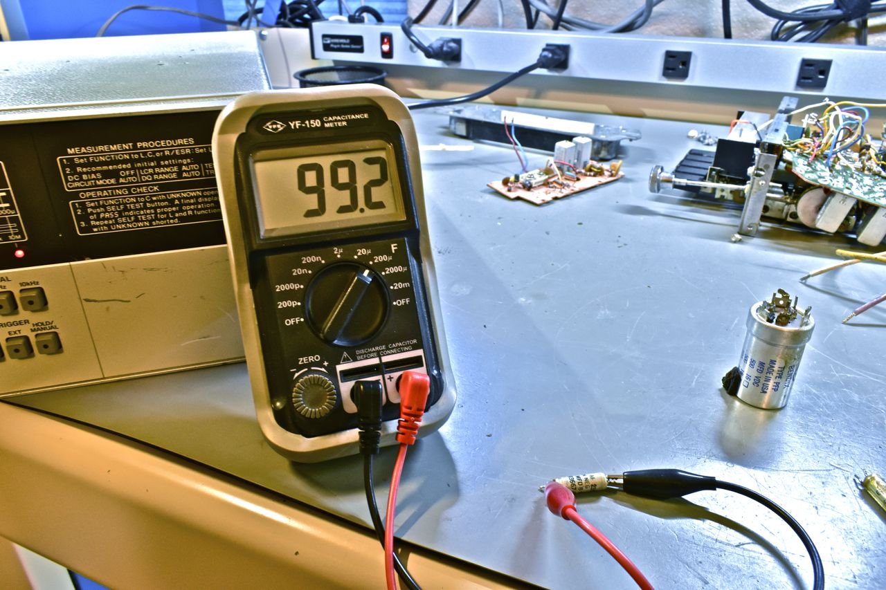
OK, onto testing. I have a little handheld capacitance meter here first. The rating on the capacitor is only 50 uF. If this is all you had, you might think this is an over achiever and is still good. At this point I wish I could insert Dr. Cox's wrong song from Scrubs.

Here's the same cap on a lab grade LCR bridge. It's a little high, but not terribly. So what's going on here and why is the capacitor still bad.
Well it's about the ESR or equivalent series resistance. Imagine there is a resistor in series inside the capacitor. Ideally the series resistance should be 0 ohms, but in reality for a capacitor like this it should be 1/2-1 ohm, 2 ohms max.
Now from the D or Q reading we can use some simple trig to calculate ESR.

Or just press the ESR button and it does it for you. So 14 ohms is way too high. This capacitor is still alive, but it's dying and very much on its way out.
So why does the handheld capacitance meter read nearly twice the rated capacitance?
I should note it isn't because the handheld is some cheap thing, I've seen way overpriced Fluke handheld multimeters with a capacitance function give the same B.S. result.
The answer is simply how it measures capacitance. The handheld meters are applying a charging voltage to the capacitor and integrating that over time to calculate capacitance. What happens when the series resistance goes up..... it takes longer to charge the capacitor and fools the meter into thinking it's a larger capacitor than what's actually connected.
The big LCR bridge is using frequency applied across the capacitor to determine is true capacitance and that method is unaffected by any resistance.
There's the reason why. Hopefully that makes sense.

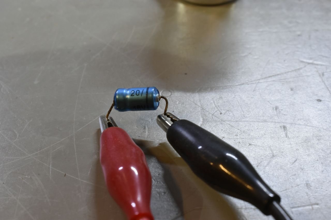
Lets test the other capacitor on the AM board. This is the filter capacitor in the AM B+ supply and is circled in green.


I'm going to keep using both meters to show how easily it is to be fooled.
So this is saying it's 26.1 uF and it's rated at 20 uF. So that seems good, or does it....

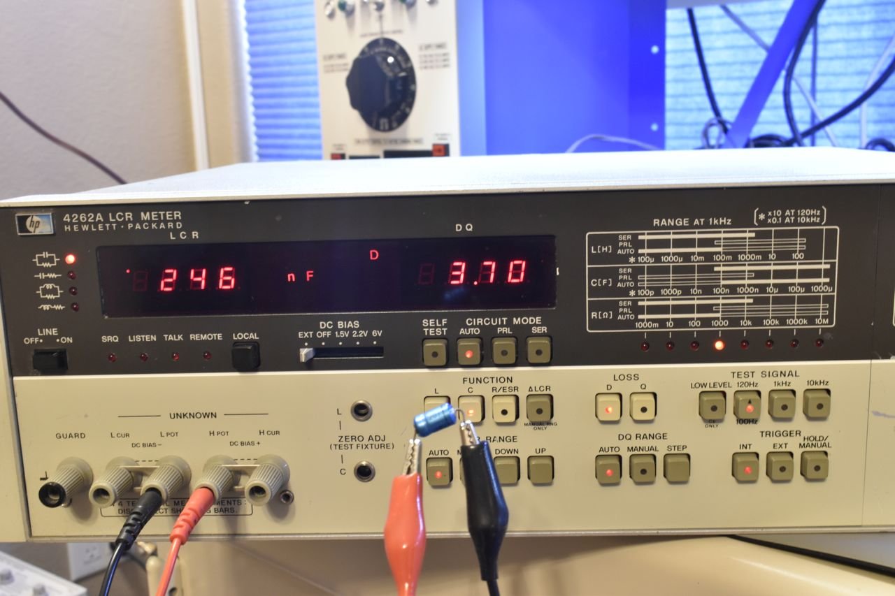
Oh my it's real value is 0.246 uF. It's dead. Nobody home. Why did the handheld read nearly ok then.

Because the ESR is really high at 1.3k ohms. By sheer dumb luck the tiny residual capacitance this had left and the high ESR it had fooled the handheld into thinking it's close to the rated value.
Having this capacitor open and running in a car with all the electrical load noise would have probably made it next to impossible to listen to AM. This also could cause unwanted oscillation or spurious squealing. Since I initially tested this on a clean lab supply there is no electrical noise and the AM radio portion worked with the spectrum analyzer.
Click here to continue to part 8