1968 Ford AM-FM Stereo Overhaul : 09 Repair - Testing Capacitors Continued
2023, November 14
1 - 2 - 3 - 4 - 5 - 6 - 7 - 8 - 9 - 10 - 11 - 12 - 13 - 14 - 15 - 16 - 17 - 18Radio Overhaul - Repair page 6
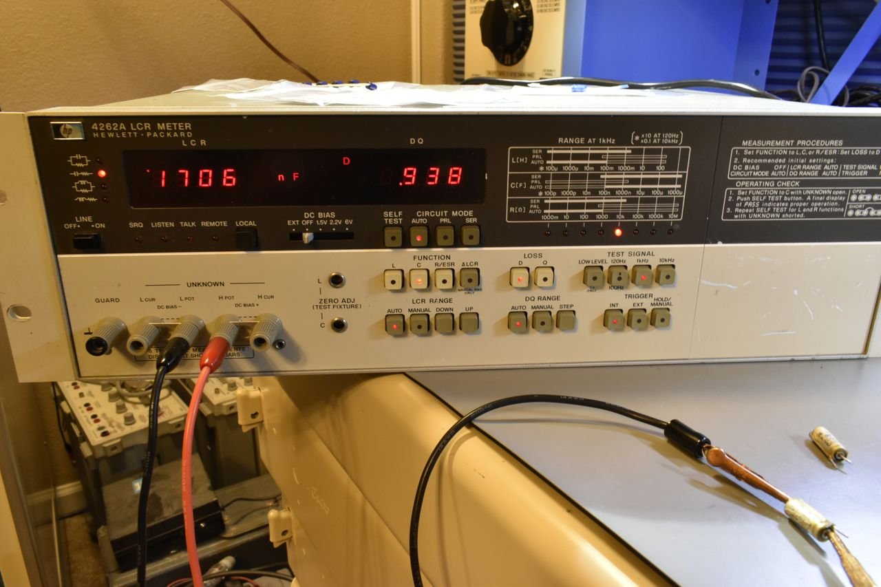
The industry standard is 120Hz. Why 120Hz... because the North American power grid operates at 60Hz and capacitors used after a full wave bridge rectifier will see 120 Hz pulses of current, which is a common application. My HP LCR bridge can measure at 120Hz, 1kHz and 10kHz. Now healthy capacitors will operate near their rated capacitance (usually around 1% variance) at higher frequencies, but what about old failing capacitors....
Let's take a look. This is the audio coupling capacitor again.

On 120Hz, it's measuring close enough to 2.6 uF.

At 1kHz it's measuring 1.7uF

And at 10kHz it's only 0.9uF.
Where these are used in the circuit, if you change the capacitance or resistance, you effectively are changing the allowable pass band of certain frequencies, just like what an equalizer does. Now imagine an equalizer that changes automatically on its own with frequency of the audio coming through it. It would sound terrible. Well that's what's happening here with these old capacitors. Whilst they work, they sonic quality is severely degraded.
The other audio coupling capacitor is in similar condition so no need to show that.
The last group of electrolytic's to check are the ones circled in orange.

These in this circuit function as emitter bypass capacitors. In other words they shunt the AC audio signal past the biasing network of resistance allow the proper quiescent DC biasing voltages to keep the output transistors operating near their ideal current conditions.
If these capacitors start to go open then the gain falls off severely in the audio amp. Which is exactly what this radio was displaying when I powered it up as you had to nearly max the volume control out to hear normal listening level. With that I already expected these to be dead or nearly dead.

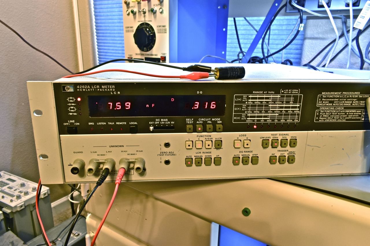
I'll be honest I wasn't expecting that. I mean they are just a pile of bones dead.

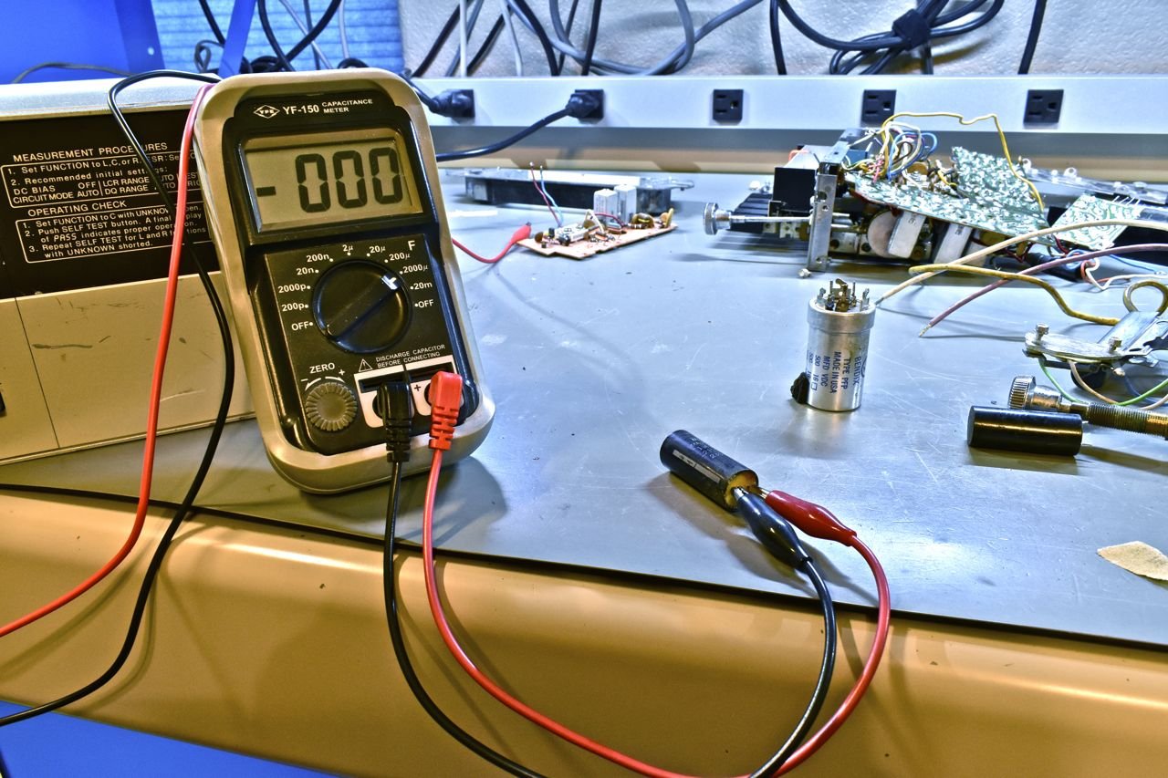
The LCR bridge says 0.0076 uF and they are rated at 1000 uF. I guarantee that tiny capacitance is from the test leads and not the capacitor.
This is the one time the handheld and the bridge were in complete agreement.

Holy cow it's no longer a capacitor but a 550k Ohm resistor.
The other one was no better and certainly no worse. I mean 0 is 0.
That concludes the learning curve on electrolytic capacitors. I know I covered a great deal (and still left a great amount out), but hopefully some will find this useful.
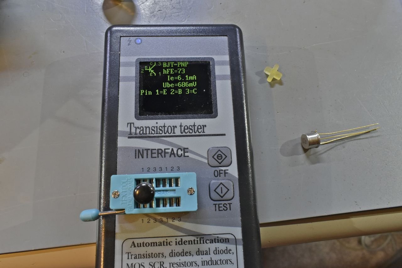
Last item on the bucket list was the driver transistor for the stereo lamp. The resistor in series with the emitter checked fine so I did a quick test with a pocket checker.

Now this can also be like the handheld capacitance meter. You need to be aware of the equipments limitations and how exactly it's testing the part. On the surface this says it's just fine.
I have a curve tracer, but that's a bit much to get into, if you thought simple electrolytics was a complex subject I could drown you with bi-polar solid state theory and applications. I will say this, these early epoxy domed transistors are notorious for failure with age. And this transistor is indeed bad, regardless of what the tester says.
I think that's enough for now. On the next round, I'll cover testing the new parts, assembling and testing the radio to see how well I did to correct the first round of problems and see if any new problems are now detectable.
Click here to continue to part 10