1968 Ford AM-FM Stereo Overhaul : 18 Alignment - Lighting LED
2023, November 14
1 - 2 - 3 - 4 - 5 - 6 - 7 - 8 - 9 - 10 - 11 - 12 - 13 - 14 - 15 - 16 - 17 - 18Radio Overhaul - Alignment page 4
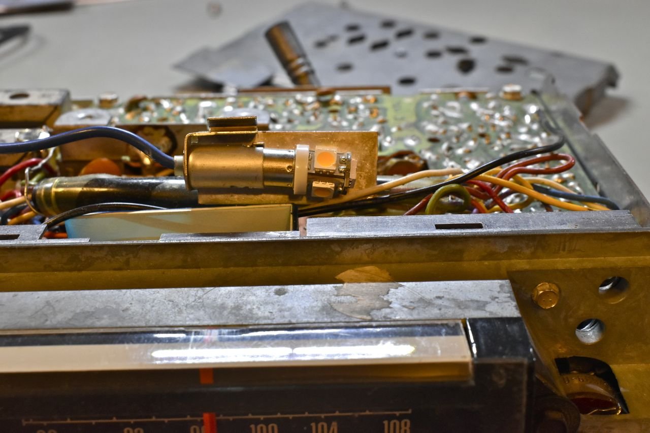
Another enhancement I made was to use a warm white LED for the radio to brighten it up.

The reason I bought the more expensive warm white LED is I like the pale green glow of the instrument cluster at night and cool white LED's would be a harsh blue glow and adding green LED's actually made the dash look evil. I never thought green anything could look so demonic, but believe me, been there tried them all.

These LED's are really bright. I used them in all the rest of the dash.

Still has that pale green factory glow, just much brighter.

These are all warm white LED's, except for the original radio still in there. The old incandescant radio backlight is barely visible. The clock is barely visible, but that's still the old clock and I have a funny feeling it's very sooty in there (cooked). My restored replacement clock ready to go in is very bright with this LED bulb.
The radio was done and ready at this point. However I had some time to think about the total audio system and not just the radio. Before I was going to use the original output transistors with isolation capacitors and impedance matching audio transformers to mate this radio to an external fader, reverberation, equalizer and finally power amplifier stage.
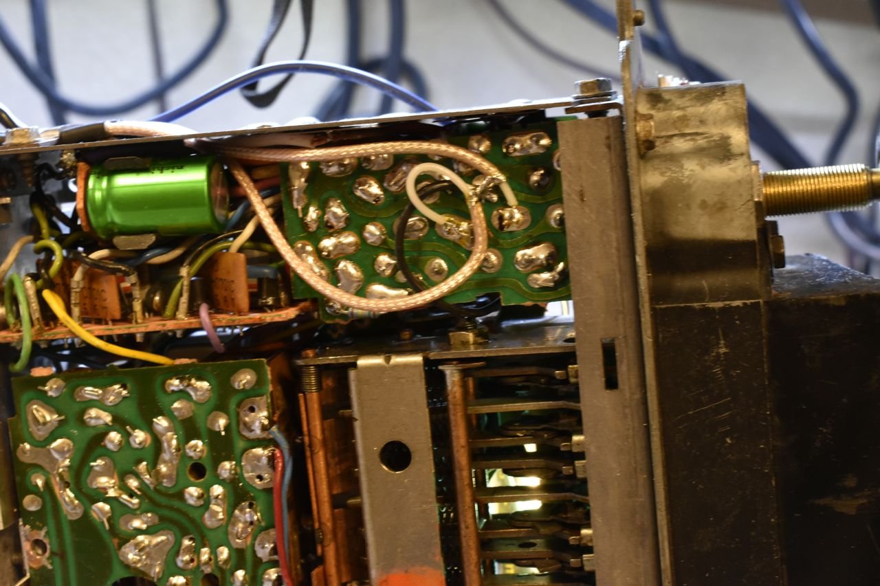
Upon reflection, I decided to just add line outs from the radio and skip the isolation capacitors and impedance matching transformers. It's just an extra set of outputs and I can still use the power amp in the radio if I wanted to for whatever reason.

Rather than RCA jacks, I decided to use BNC connections since the radio is buried up in the dash in a car with a factory centre console and factory air con. If the RCA plug should come undone, so would I in tearing it all apart again to get to it.

Simple enough to connect.

This looks pretty good.

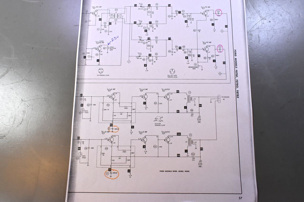
Using the line outs means I don't have to use these or have extra noise added by the output transistors and even by these components.
Now a word about why the isolation capacitors.

If you have a look at the radio schematic particularly at the output, you will see these are class A amps directly driving the speakers. Do not let the transformer near the output fool you. That's only there for negative feedback to control distortion, most of the quiescent current of the amplifier always flows through the speaker. That's why it's either A.) imperative you use the required resistance speaker or even better use an isolation capacitor in series with your speaker and you can use a lower resistance speaker without overheating the output transistors.
Cheers
‹ the end ›