1968 Ford AM-FM Stereo Overhaul : 10 Repair - Replacement Parts
2023, November 14
1 - 2 - 3 - 4 - 5 - 6 - 7 - 8 - 9 - 10 - 11 - 12 - 13 - 14 - 15 - 16 - 17 - 18Radio Overhaul - Repair page 7
This section will deal with the replacement parts. On the topic of the stereo lamp driver transistor.
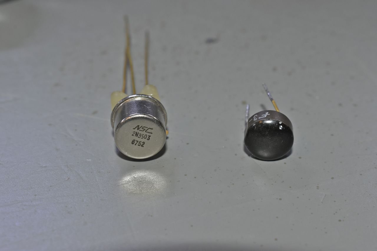
The old epoxy domed one was indeed faulty and I found a suitable one from my parts selection. All these transistors in this radio are silicon and there are no germanium ones. Now the Sams schematic is in error and shows a couple of them as germanium but they are silicon, so you can of have to use instinct to find the errors.
Germanium transistors will have a Base to Emitter forward voltage drop around 0.2 volts. Silicon will have around 0.6 volts.
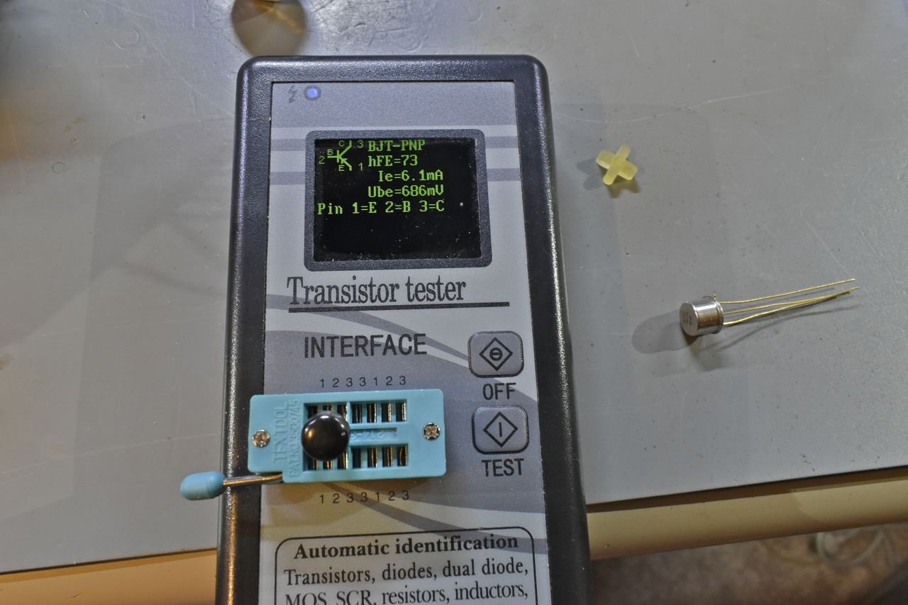
Just to rehash, this is the old lamp driver and according to this it's ok. But it's not testing under a heavy load and that's where the problem lies. In this case it's only 6.1 mA, that lamp even with the 10 ohm resistor will draw well over 100 mA. A curve tracer will confirm the collector current falls off under a heavier load.
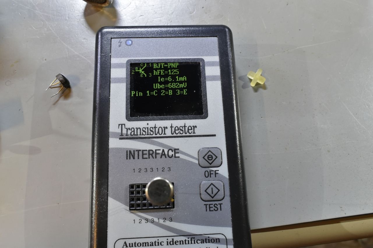
This one tests nearly the same. This kind of tester is fine for catching dead devices, it doesn't do a comprehensive test. Again it's all about knowing exactly how your test equipment operates.
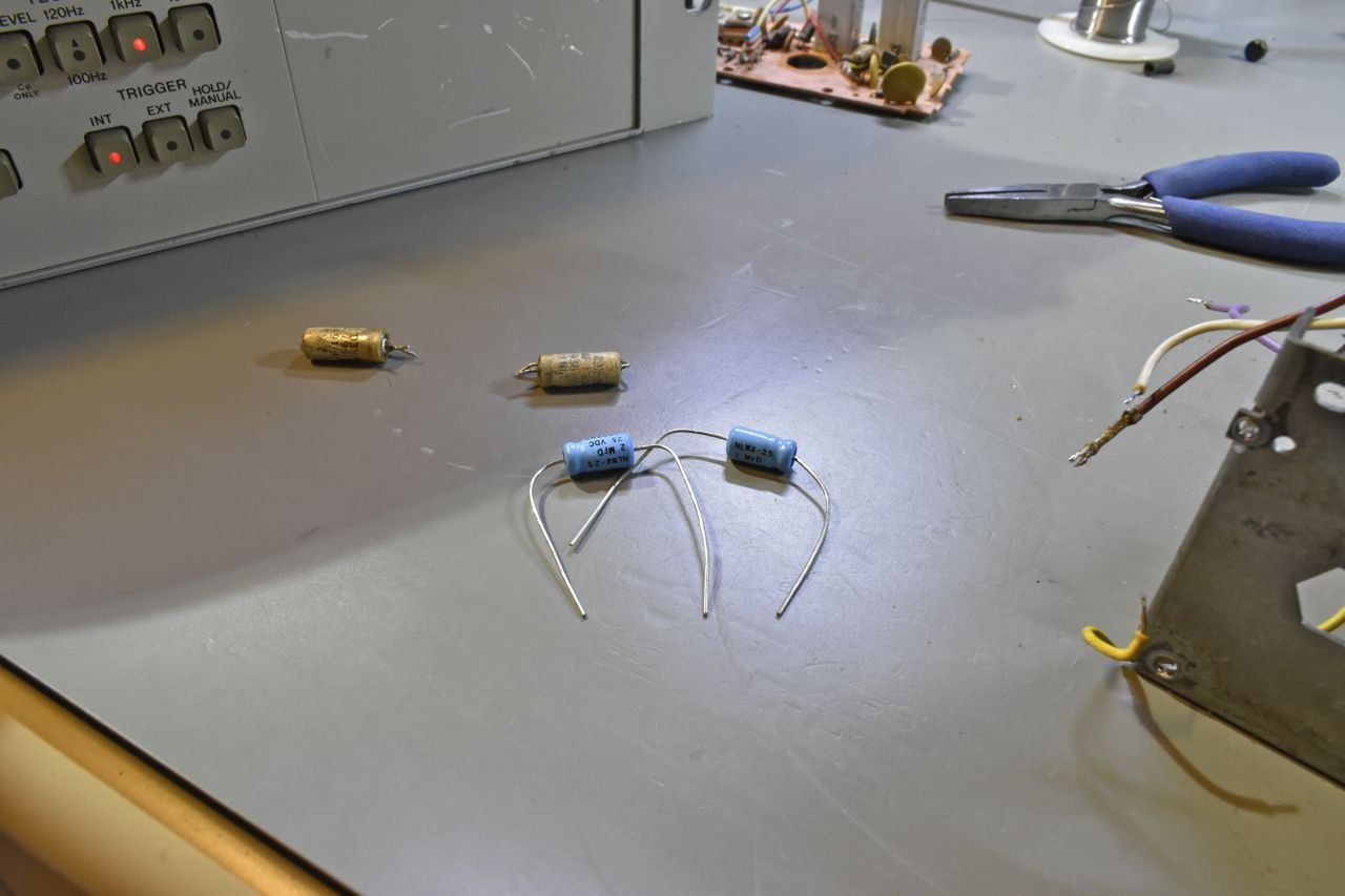
On the topic of other replacement parts, in this case capacitors, with the current supply shortage, finding the perfect part replacement was a bit of a challenge as the major parts houses I listed earlier were really skint on inventory and I didn't want to wait 16-30 weeks, in this case I settled for electrically critical criteria but had to settle in some cases for case size or just pricing. In this case these capacitors replace the audio coupling caps from earlier. These were over 7 dollars each.
I will not bore you with more capacitor testing pictures. The handheld meter does agree with the LCR bridge on the new capacitors. My previous pictures were to demonstrate how easily it is to be fooled by readings with failing parts.

These are to replace the main power supply filter capacitor can. Here's where you have to think out of the box a bit. There are the equivalent of three capacitors in that can. Finding a replacement can that fits in the radio will be next to impossible. The only multisection can capacitors that are still being made are mostly reproductions for old tube gear and those are physically much larger and higher voltage.
About replacement capacitor and voltage ratings. Whilst you never want to put a lower rated capacitor in place of a higher rated voltage one, on the flip-side you do not want to put a really high rated voltage capacitor in place of a lower rated one. The reason is electrolytic capacitors occasionally need to 'reform'. When an electrolytic capacitor is dormant for long periods the dielectric insulator starts to break down in some areas. When you apply voltage to a dormant electrolytic capacitor it can heal itself. But you need to be ~1/2-3/4 of the rated voltage to do so.
So you wouldn't want a 100 volt capacitor for the 16 volt filter capacitor sort of thing. Just something to keep in mind.
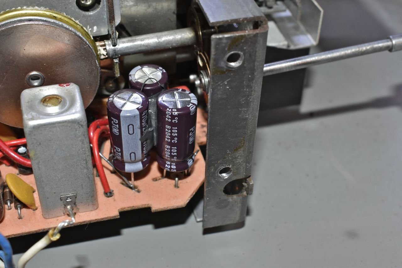
Here's how I mounted them. This worked really well. I used low acid RTV to effectively glue the three together. This makes them very stout and resistant to vibration.
You want to use low acid RTV, typically the Ultra series RTV (in this case Ultra Black) are low acid. Some other RTV's cure by releasing acetic acid and the acid will eat through some materials and you never want to use that in electronic equipment. Basically if the RTV has a strong odor, don't use it as glue.
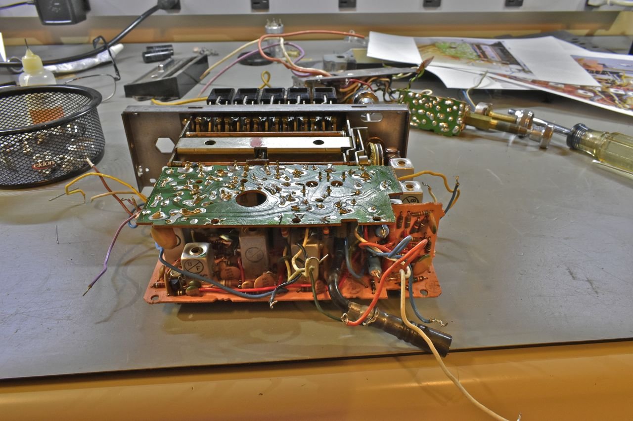
OK, so I've replaced the electrolytic's on these boards and I reinstalled the AM board.

The balance control is added. This was cleaned with Deoxit.

Cleaned and installed the front support plate.
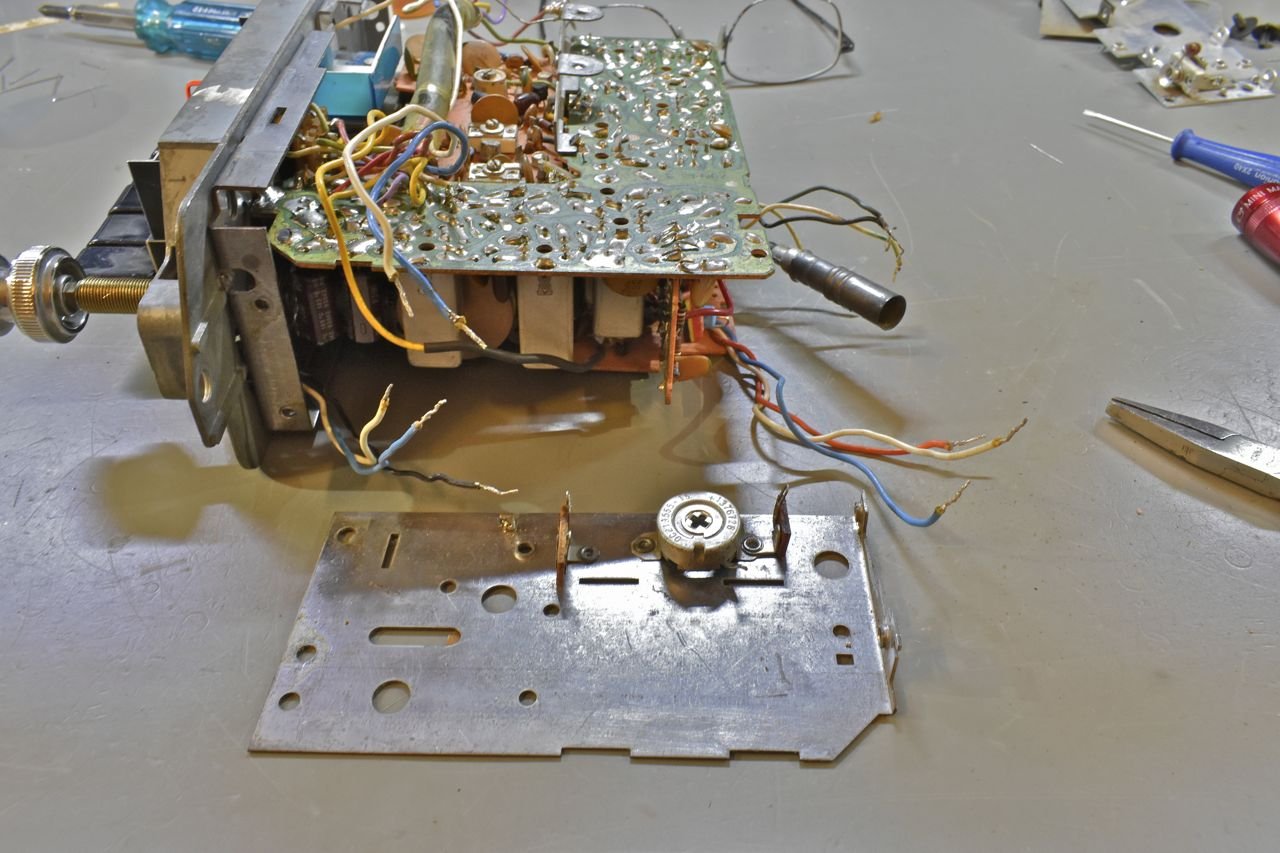
This rheostat is the stereo separation adjustment. It's adjustable from the exterior of the radio.
Click here to continue to part 11