1968 Ford AM-FM Stereo Overhaul : 02 Diagnostics - part 2 of 18
2023, November 14
1 - 2 - 3 - 4 - 5 - 6 - 7 - 8 - 9 - 10 - 11 - 12 - 13 - 14 - 15 - 16 - 17 - 18Radio Overhaul - Diagnostics page 2
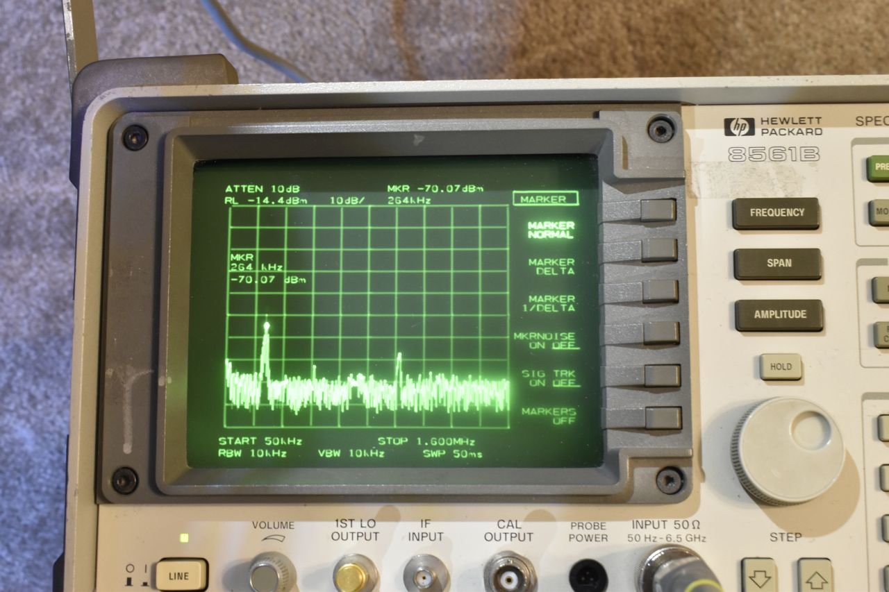
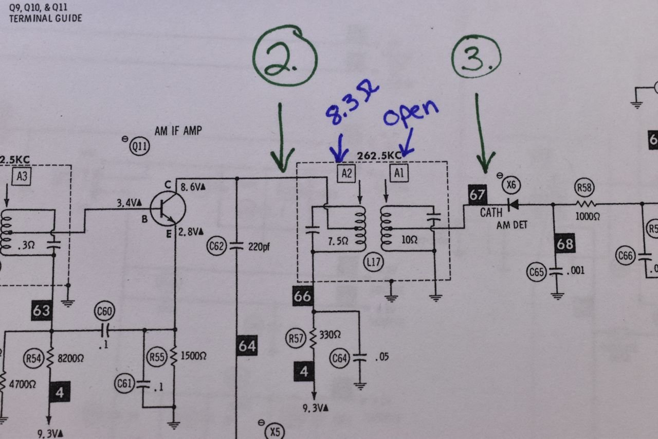
At point 3.) the signal is attenuated greatly and below the conduction threshold of the detector diode, hence no output on the radio. I checked the diode and it checks fine (diode check on a multimeter) and I checked that C65 is not shorted and it wasn't. So next I checked the resistance on the IF transformer.
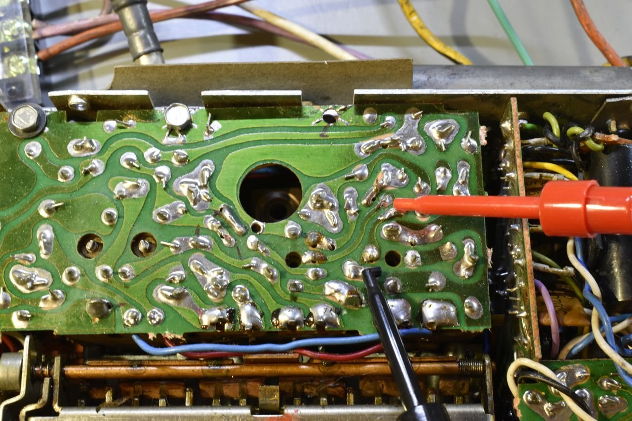
Checking the primary coil of the last IF transformer.
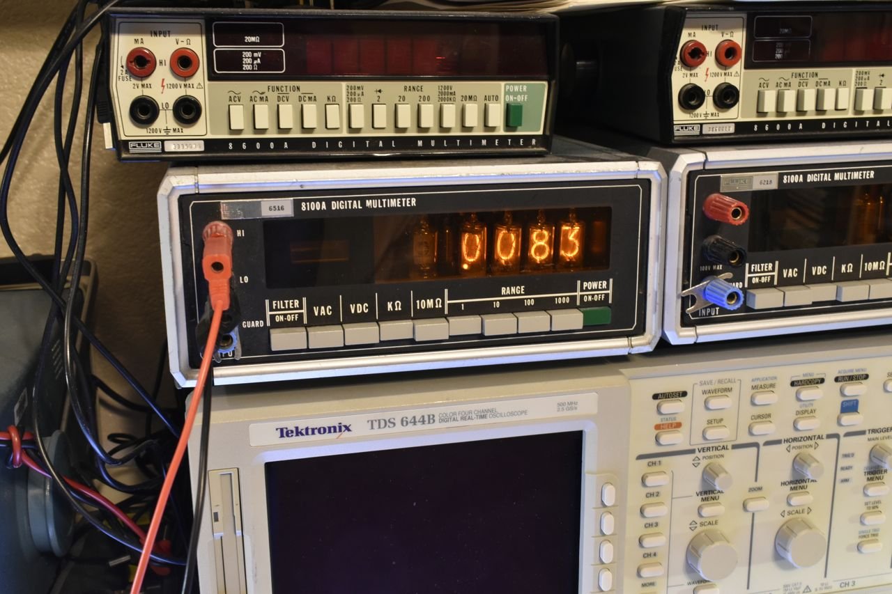
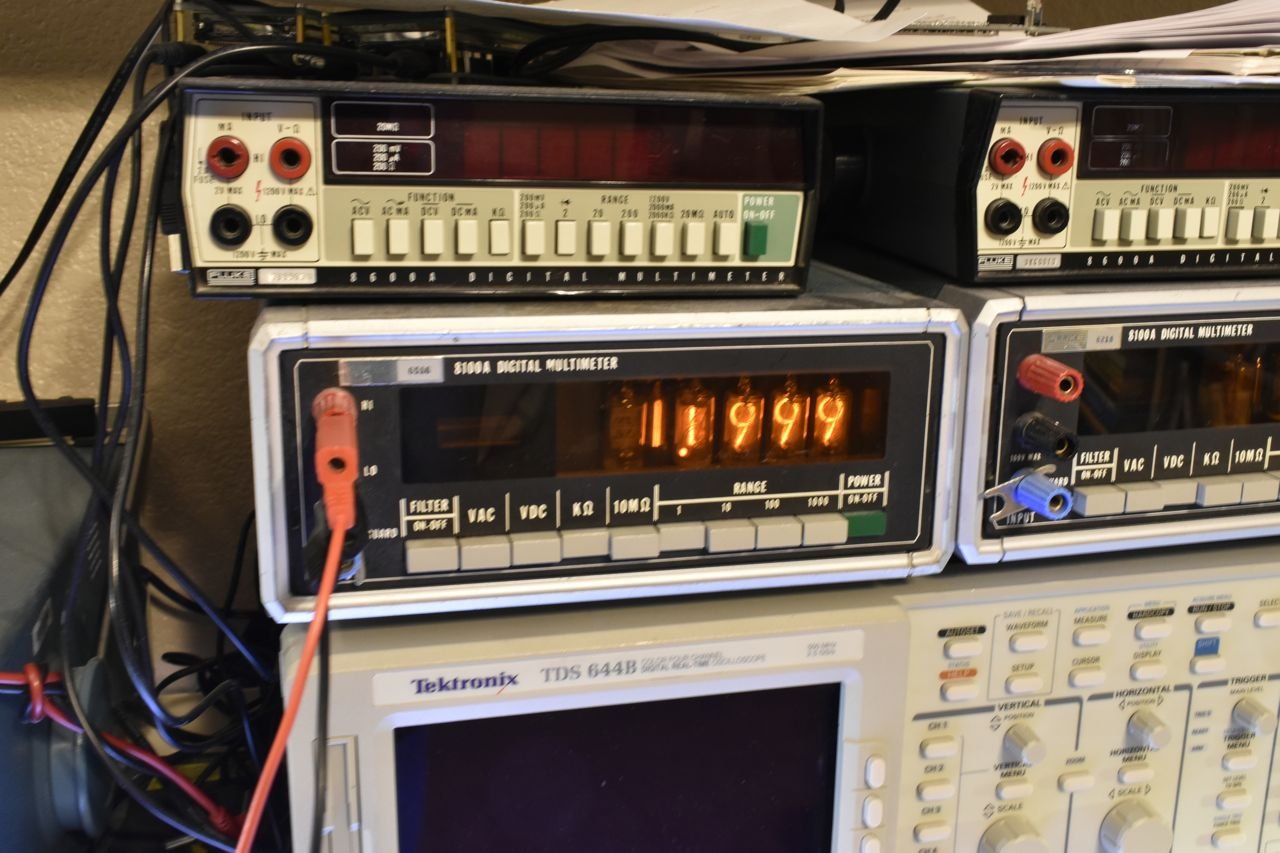
8.3 ohms. Yeah I have newer multimeters but I do like the vintage stuff when appropriate to use. These old nixie tube Flukes are from 1968 and are spot on calibration wise and never had a problem with either of them.
Anyway the schematic calls out 7.5 ohms, but I'm using a 2 wire resistance measurement so the resistance of the leads is adding to the real value some. The primary is fine.
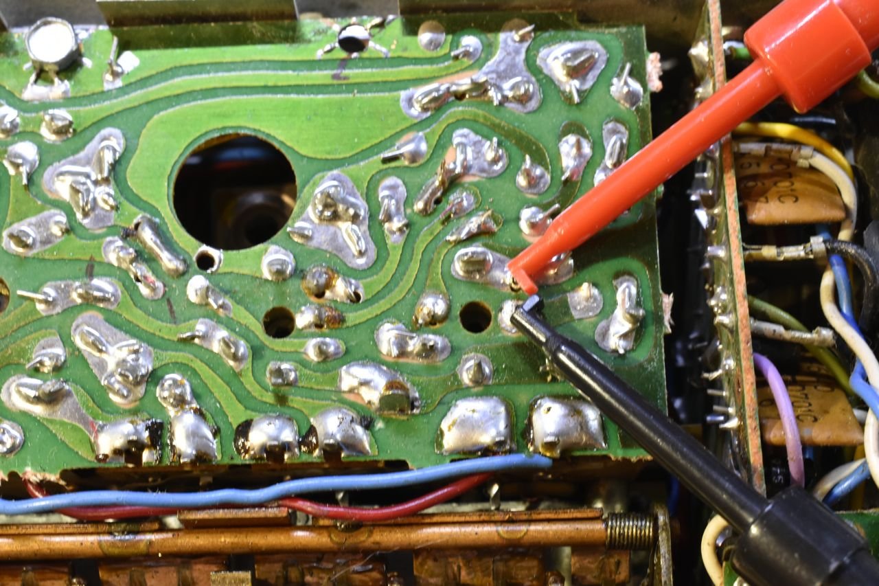
Measuring secondary.
It's open. Well there's the reason why AM is dead.
Now I know when I take the radio apart I'll remove this IF transformer and see if I can't repair the broken winding. Now if I listened to the internet I would have taken the radio apart, replaced all the electrolytic's then put it all back together, only to have to take it apart again to fix this. Once you better see what it takes to take apart and put back together you'll really understand why it's important to diagnose first what you can, before you attempt any repairs.
Onto the FM stereo portion and giving it a once over to see why the FM radio is alive but not the stereo lamp.
This operation does require some specialized kit.
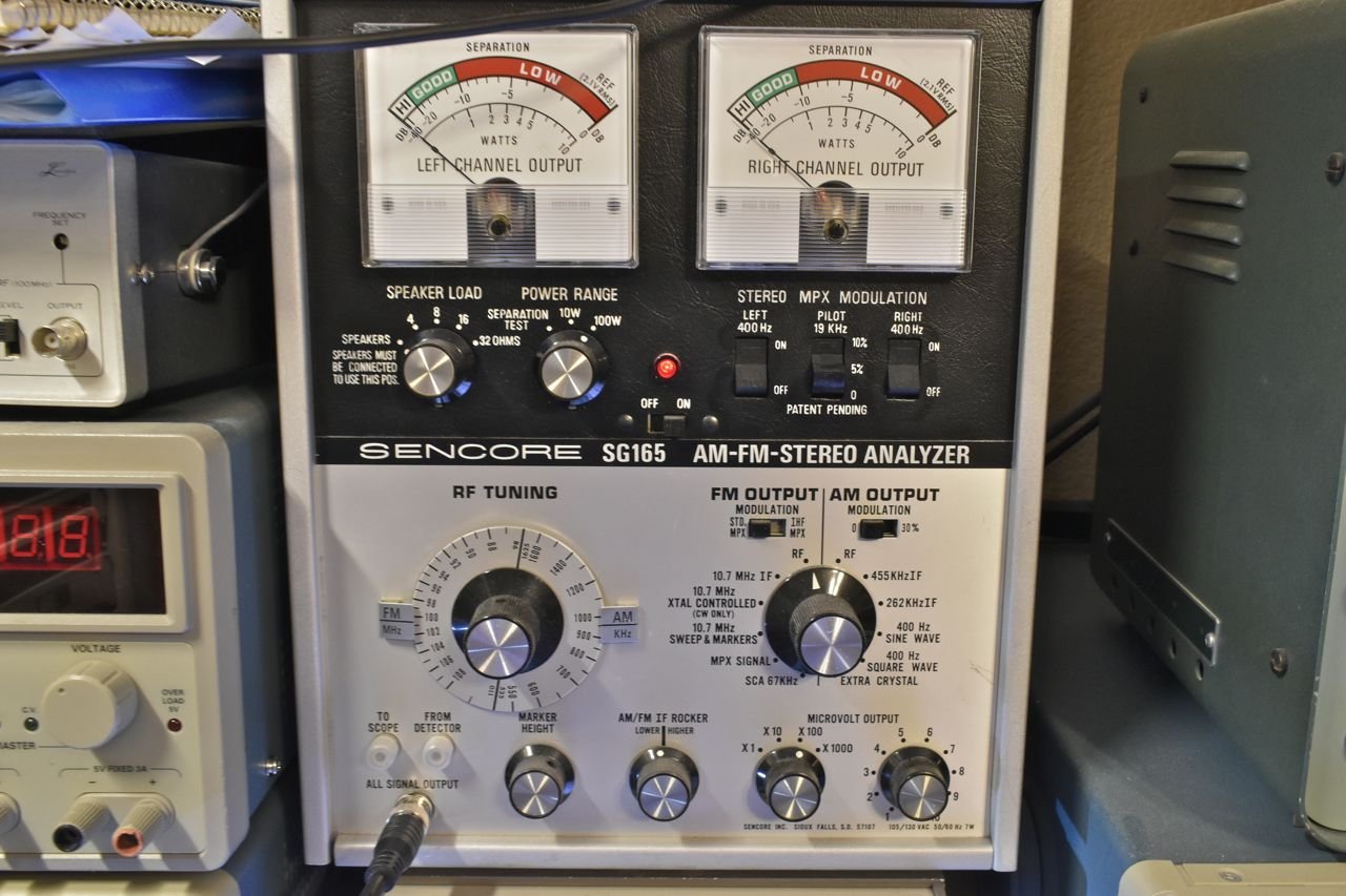
In this case I am using a Sencore SG-165. Sencore did make a more modern version of this it's an SG 80 I believe. There are also some other brands. I have a Leader stereo generator as well, but it doesn't have all the functionality of this Sencore. The big problem with older test gear is that often it's either out of calibration so much it's not useable or it's failed and out of calibration to boot. Then it costs even more to repair and get it to the point of using. I've already went through and rebuilt this Sencore and calibrated it.
How this works; with this function selected, it will generate an FM station frequency based on the setting of the big round dial (88-108MHz) and then you can manually turn on the stereo pilot and also the left and/or right speaker test tone. The output of this is fed into the antenna of the car radio and you tune the car radio dial to whatever this is set at station wise, or vise versa, doesn't matter. Then you can turn on the stereo pilot frequency of which should turn on the stereo lamp but otherwise the speakers should be silent and then you can turn on the left speaker or the right speaker test tone or both to check stereo separation.

So here's the setup, since both amplifiers in this radio are so neutered (way less than 1 watt) I am using the Fluke multimeters to measure the AC signal across the speakers. I have the car radio tuned to the stereo generator.

I have the stereo pilot on and the right side speaker tone on.

I have right side speaker with a decent amount of separation. There's a little on the left.
Click here to continue to part 3