1968 Ford AM-FM Stereo Overhaul : 15 Alignment - FM IF Section
2023, November 14
1 - 2 - 3 - 4 - 5 - 6 - 7 - 8 - 9 - 10 - 11 - 12 - 13 - 14 - 15 - 16 - 17 - 18Radio Overhaul - Alignment page 1

This is the FM IF section. This is the bandpass of the entire IF chain just before the FM detector. The FM IF bandwidth should be 150 KHz wide. I fiddled with all the adjustments (ferrite screws in each of the FM IF transformer cores) until I was rewarded with (or so I thought) a good looking spectrum. You can see the middle 10.7 MHz marker and the +/- 75 KHz side markers on the outer edge of the slopes. It's textbook.

This is the detector waveform, again close to textbook, just a tad off but it's as close I could get it and centre the 10.7 MHz marker.
However whilst all this was textbook adjustments the real world had other ideas. This killed the sensitivity of the FM. It would only pick up nearby stations. Using the signal injection, it was only picking up stations with 50 or more uV and those had static and the FM stereo decoder wouldn't work until closer to 100 uV signals were injected. For reference you should be able to hear FM stations, even if not perfectly clear with around 10uV on the antenna and it's OK if the stereo decoder doesn't engage.
With that I went with Plan B and adjusted the FM IF and detector for maximum sensitivity and good separation, so all by ear and not pictorial scope displays. I was able to get decent FM (Monaural) all the way down to 7 uV and stereo reception around 30 uV. That's a world of improvement.
OK, so why bother with textbook examples if adjusting for the peak works. In this very particular case, peaking the FM IF still allowed enough bandwidth through to allow stereo reception.

Here's a breakdown of the typical FM station bandwidth (all 75 KHz). Here's a little explanation of it. If you had an old monaural pocket FM radio it would utilize the first 15 KHz of the total information on a single station spectrum because the left + right audio information is contained there. This also applies to stereo receivers with too low a signal to activate the stereo decoder, all they use at that point is first 15 KHz. The 19 KHz pilot is what the stereo decoder looks for to activate. If the signal is too weak, the decoder turns off and you can still hear the FM station, it just will be monaural. Also there are still a couple FM stations, mostly talk radio that do not transmit in stereo, so there's no 19 KHz tone present and the stereo decoder stays off.
When a strong enough stereo signal is received, the stereo decoder needs the L-R information (from 23 - 53 KHz) along with the L+R information (normal monaural information) to mathematically produce the separate Left and Right channels. I'll get into that more in a bit.
The SCA portion of the FM radio station is the piggy backed station that use to be very popular well before even cassette tapes, never mind the internet as this was an original specification of the FCC to define FM stereo broadcast and the adherence to it. SCA like I mentioned at the beginning of this thread is monaural mid fidelity station that use to play commercial free musac for places like department stores, dental offices, etc.
I do believe there are still a couple of stations that have the SCA active with another broadcast. Way back when, you were supposed to rent equipment to listen to it, but it's easy to add a PLL to a standard FM radio and listen to it with little to no cost.
The RDS section was added a couple decades ago, there was juuuuuuuuust enough spectral space to add a carrier for digital information. This is what carries the information on car radios that tell you what song is playing. Obviously the station is sending this information along with the audio.
Now back to this little Ford AM-FM stereo radio. For the FM stereo to work the bandwidth of the IF doesn't need to be textbook 150 KHz/2 wide. It only needs to be 53 KHz wide for the AM-FM stereo portion to work. So if peaking the FM IF results in more sensitivity but narrower, it will work better so long as the IF is at least 53 KHz x2 wide.
At this point, the FM radio front end was done, but I needed to adjust the stereo decoder. But first here's a quick review of how stereo actually works. This is from Sencore SG-165 manual. It's simple to understand so why not have a look.

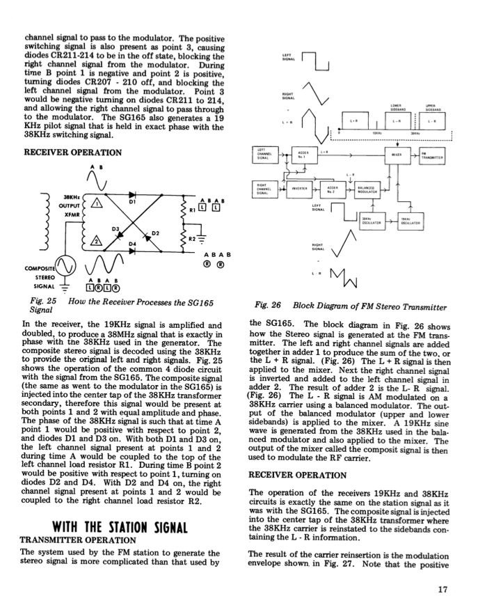
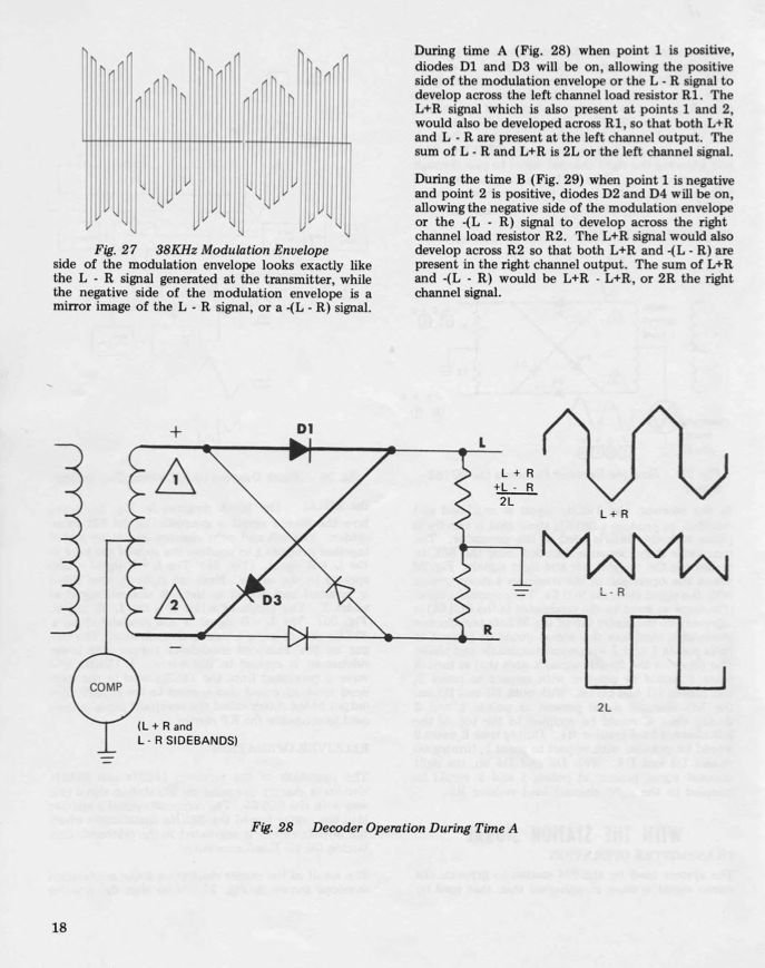
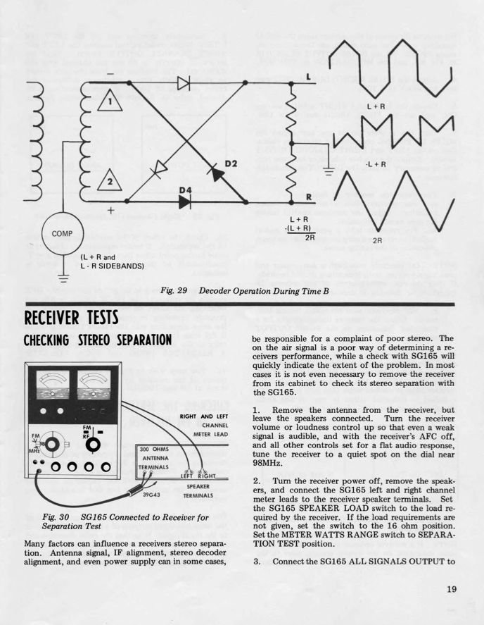
It's a simplistic explanation, but that's all one needs to do the alignment. Designing your own would be beyond the scope of this thread.
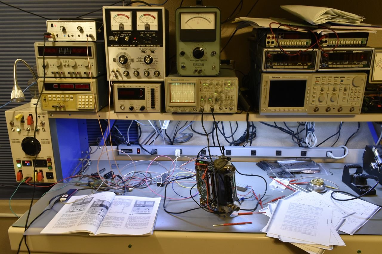
At this point, I used 2 channels on the scope; one for left channel output and one for right channel output, then just injected the stereo signal on the antenna (basically acting as a radio station but I can control the left and right audio being transmitted).
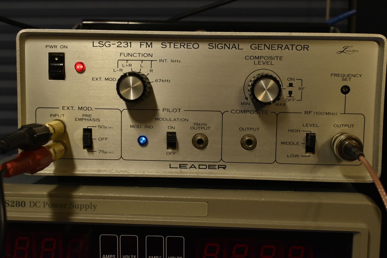
I only have two pieces of equipment that can do this. This is the Leader. It is currently set to send a 1KHz audio tone on both L and R channels in stereo (19 KHz pilot active by blue lamp). The Leader only transmits on one equivalent FM radio station which is 100 MHz.

The radio is tuned to 100 MHz and the stereo lamp is on, which it should be with the 19 KHz pilot signal on the Leader.

OK, you can see both channels (L & R) of the radio on the scope. And you can see the vague hint of stereo choppiness in the sine waves. That's the 38 KHz chopper working in the stereo decoder. Humans can't hear it, but I bet it drives dogs and cats insane if the tone controls, audio amplifier and speaker are allowed to reproduce that high.
Click here to continue to part 16