1968 Ford AM-FM Stereo Overhaul : 12 Repair - Volume Control Testing
2023, November 14
1 - 2 - 3 - 4 - 5 - 6 - 7 - 8 - 9 - 10 - 11 - 12 - 13 - 14 - 15 - 16 - 17 - 18Radio Overhaul - Repair page 9
To address the first problem, I set up the stereo generator with both test tones on so the input signal was equal on both speakers. Then with a steady signal I took some measurements to figure out why the right side was louder. I could be partly the stereo decoder, it could be the volume/tone controls, and or it could be the amplifiers as the gain may be higher in one than the other.
Didn't take long to find the problem.

These are ac voltages from the test tones entering the volume/tone control circuitry. To make sure the amplifiers weren't dragging the signals down I removed the disc capacitors with the red X through them. From this you can see at the balance control I only have a R & L difference of ~ 1%. At the input to the amplifier section (out of the volume/tone controls) I have roughly 45% difference between R & L. Here's the problem area.
I removed all the film capacitors from this area to check for leakages, although film capacitors rarely fail. I checked the resistors and they all checked ok. Although some of the film capacitors were crumbling. So they will get replaced because they are physically falling apart.
The problem was the actual volume controls themselves. Das ist nicht sehr gut. That's not good because they are very specialized controls for this particular radio design and not something that can be just purchased.
Looking at the schematic you can see the end to end resistance is supposed to be 225 k Ohms with a tap at 75 k Ohms.
Here's my results.
Right side volume control potentiometer:
Full range Ohms: 319 k (supposed to be 225 k) Tap to audio source end Ohms: 242 k (supposed to be 150 k) Tap to ground end Ohms: 77 k (supposed to be 75 k)
Left side volume control potentiometer:
Full range Ohms: 211 k (supposed to be 225 k) Tap to audio source end Ohms: 131 k (supposed to be 150 k) Tap to ground end Ohms: 81 k (supposed to be 75 k)
So you can see if you add the tap to one end and the tap to the other end resistance that should total close to the full range ohms of the volume control.
Lets have a better look at the volume control and where the tap is at.
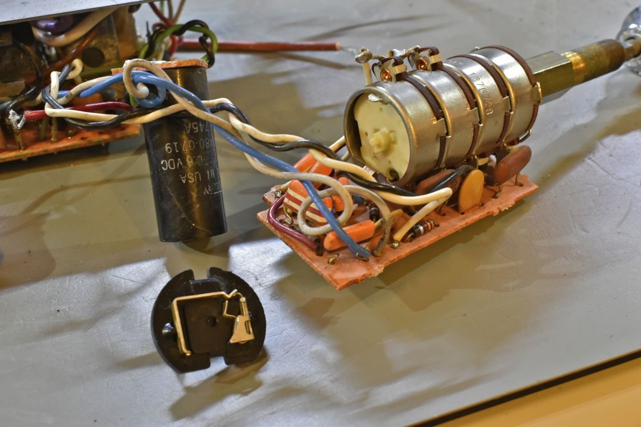
You can see the four stacks of controls amalgamated into one unit. The front two sections are the tone for the R & L side, the rear two sections are the volume controls for the R & L side. You can see the tap connection atop and to the one side. The wiper and end contacts are on the bottom on all 4 sections.
I do have the spare radio so it might be a donor candidate. With that I took it apart to measure its controls.
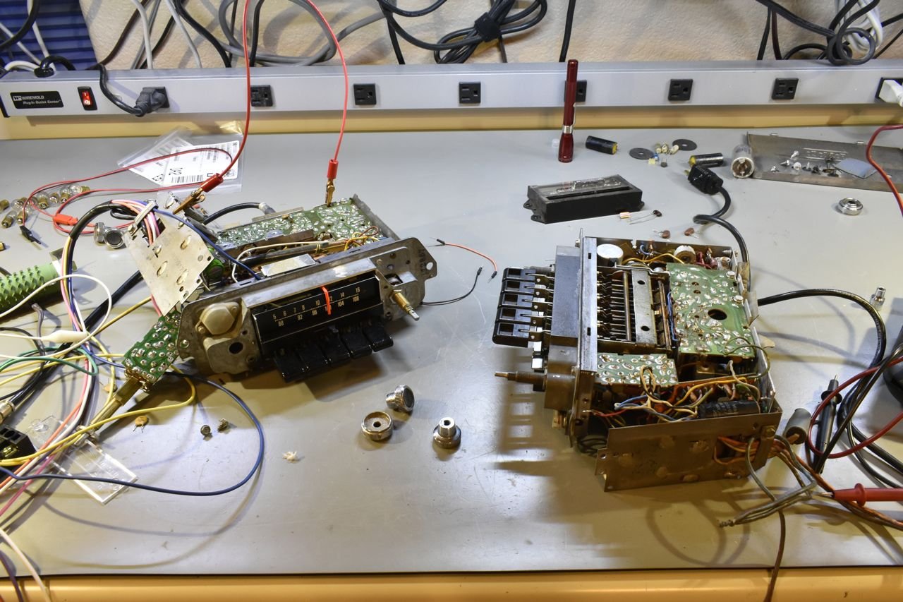
Well that took bit of time, but here's the parts radio results.
Right side volume control potentiometer:
Full range Ohms: 192 k (supposed to be 225 k) Tap to audio source end Ohms: 136 k (supposed to be 150 k) Tap to ground end Ohms: 57 k (supposed to be 75 k)
Left side volume control potentiometer:
Full range Ohms: 260 k (supposed to be 225 k) Tap to audio source end Ohms: 1621 k (supposed to be 150 k) Tap to ground end Ohms: 99 k (supposed to be 75 k)
I think the parts radio is actually worse off.
Well..... crap!
Here's where you have to think out of the box again. I have accepted I'll probably never find a decent donor part so I have to work with what I have. What I can do is try to normalize both R & L potentiometers to the least resistance portions of each other.
Let me explain that, since each volume control is divided (unequally) into two sections by the tap, I can focus on the resistance from the tap to the audio source end connection on both volume controls and whomever has the higher resistance will be reduced to match the lower resistance of the other volume control. And you do the same with the other side of the tap.
A diagram may be better:

Here I've drawn both volume control potentiometers atop the page. The blue ink represents the measured resistances of the two sections of each volume control.
Let's look at the lower section from the tap to the bottom terminal. On the right it's currently 77 k Ohms and on the left it's currently 81 k Ohms. The idea is to reduce the 81 k Ohms to 77 k Ohms by adding a parallel resistance. Then you do the same for the top portion. In the end both volume controls will measure the same across their terminals. Now this isn't exact as wiper in the potentiometer will not track exactly, but it will be close enough to improve this situation.
The equations at the bottom are just simple parallel resistance calculations to determine the extra resistors I need to add to each volume control.
After adding the resistors this is the new measurements based on % of volume control.
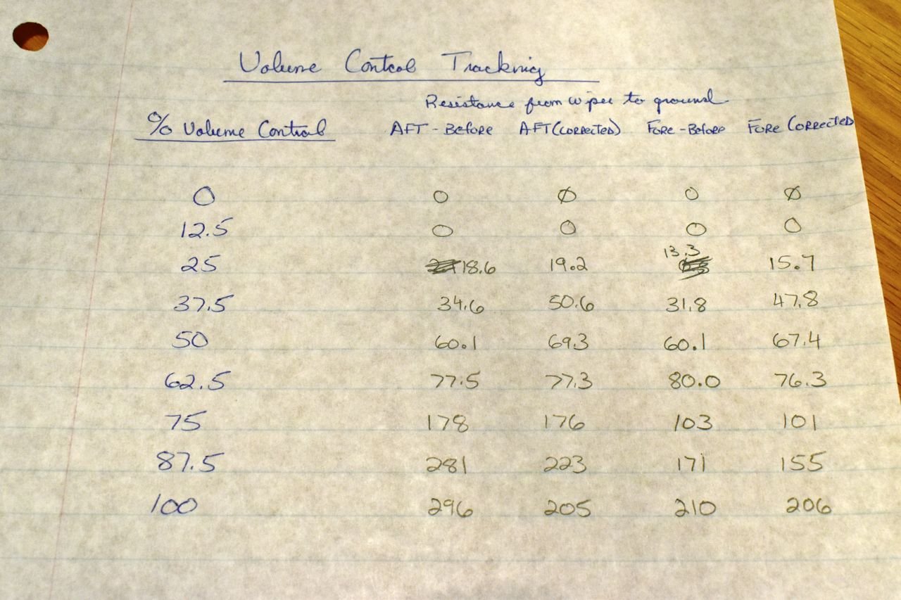
Pardon my handwriting. Aft and Fore refer to the volume controls as positioned in the radio from the front to back. You can see the L & R now track each other pretty decently till about 63% of travel on the volume knob. And after running the radio, anything past 50% is just distortion anyway and bloody loud as the amplifiers are clipping.
So this will work just fine.
Next I'll tackle the second problem of why is the audio so flat. Looking at the broader picture as in not just the radio, but the whole system as installed in the car, I am not taking into account the original type speakers used. Chances are they would have been paper cone high efficiency speakers (greater than 100 db per 1 watt at 1 meter). New speakers today aren't that efficient, mainly because there's no need to make them efficient as audio power is aplenty these days. But in the vacuum tube/valve era and early transistorized radios power output was expensive and heavy, so it made sense to make efficient speakers to make the most out of the little the radios were able to produce in terms of power output.
It is very possible the original speakers greatly accentuated the mids and highs and what seems like a flat response to me using a high quality monitor type speaker isn't what you would have heard in the car when the entire system is considered.
That begs the question, is this flat response built in or a fault?
Only one way to find out and that is model the volume/tone controls in SPICE and run an AC analysis and look at the frequency response.

I have the original circuit here. Just need to draw this in SPICE.
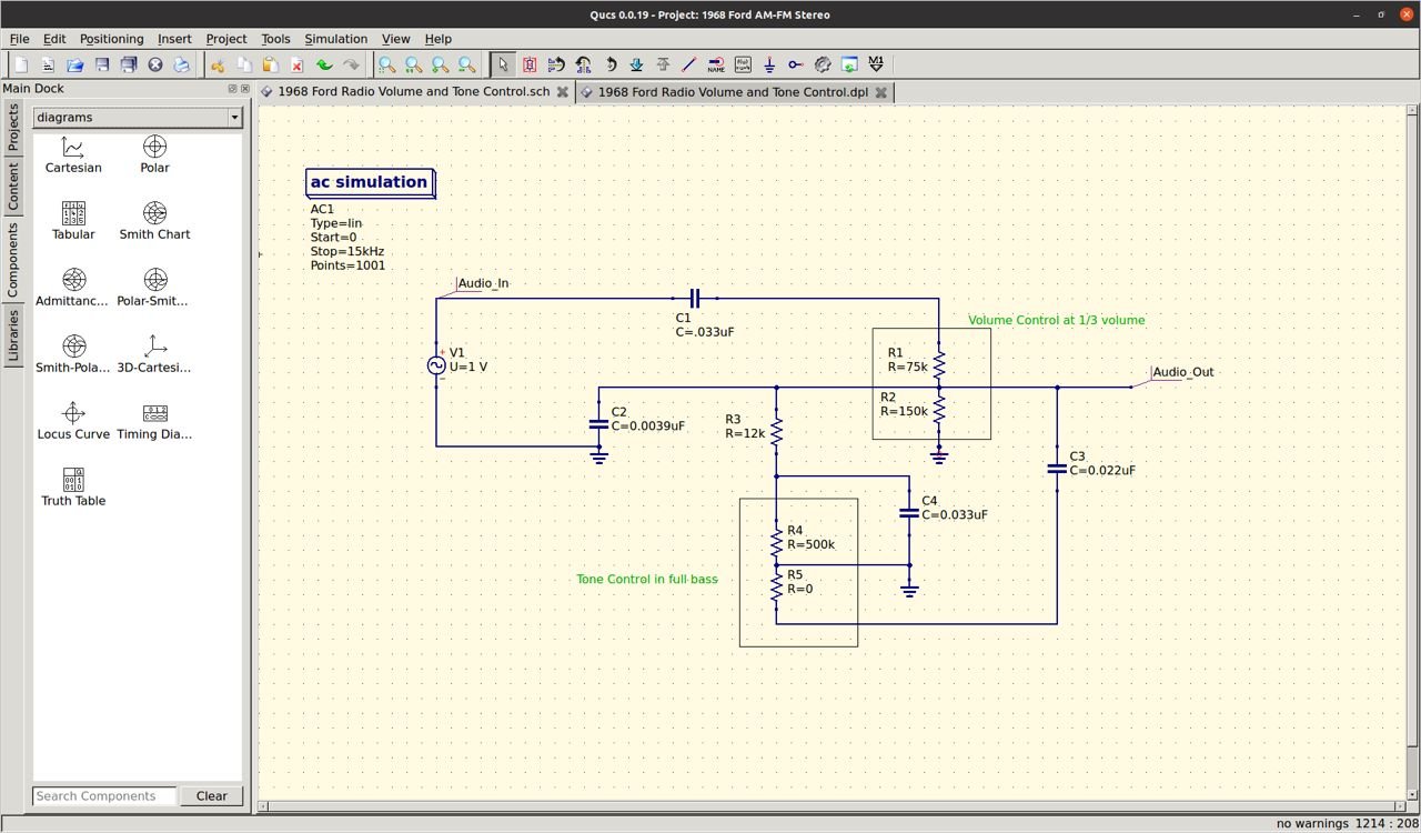
For those wondering what this is about, SPICE is circuit emulator. It allows you to test your circuits under different conditions to see how well they work before you even build a prototype. It's handy.
SPICE stands for Simulation Program with Integrated Circuit Emphasis, although you don't have to use integrated circuits, you can model discrete components as well like this simple volume and tone control.
The program I am using is freeware and is it's call Quc's. I have a couple computers loaded with Ubuntu on them and Quc's is in the Ubuntu software store for free. Just search download in the Linux free app store. Last time I checked Quc's did not run natively on Mac OS. You'll have to use Wine to run Quc's on a Mac. It does run natively in Windows as well. Although the last time I used Windows the operating system was XP 2nd edition. I probably wouldn't recognize the latest edition of Windows if I tripped over it and believe me I'm grateful.
Ok, back to the simulation. Here's how this is setup. On the input I am applying a 1V AC signal on the (Audio In) that varies from 0 to 15 kHz and it'll plot the output at (Audio Out).
In this circuit rendition, you'll notice I have the tone control set at full base (full anti-clockwise) and volume at 1/3.
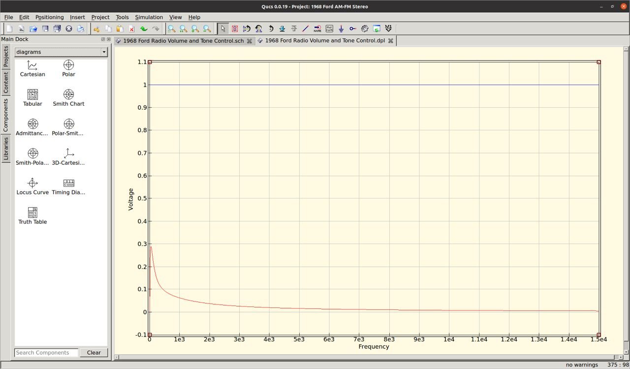
This is the audio spectrum sent to the amplifiers in the radio. From about 3 - 15 kHz it's pretty darn flat. Let's focus on the lower end and enhance that.

So in full bass setting that's exactly what it's doing, allowing more bass signals to get through and attenuating the rest of the spectrum. Still pretty flat otherwise.

Here I've set the tone control in the middle. Let's see the result.

The bass stays more or less the same but the rest of the spectrum is elevated. So this would boost the mids and highs together. Still pretty flat.
Click here to continue to part 13