1968 Ford XL Repairing Whilst Keeping It Roadworthy : 24 Hoses & Wiring Tidy-ing
2023, November 14
1 - 2 - 3 - 4 - 5 - 6 - 7 - 8 - 9 - 10 - 11 - 12 - 13 - 14 - 15 - 16 - 17 - 18 - 19 - 20 - 21 - 22 - 23 - 24 - 25 - 26 - 27 - 28 - 29 - 30 - 31 - 32 - 33 - 34 - 35 - 36 - 37 - 38 - 39 - 40 - 41 - 42 - 43 - 44 - 45 - 46 - 47 - 48 - 49 - 50 - 51 - 52 - 53 - 54 - 55 - 56 - 57 - 58 - 59 - 60 - 61 - 62 - 63 - 64 - 65 - 66 - 67 - 68 - 69 - 70 - 71 - 72 - 73 - 74All this wiring is extra crispy so it all needs to be replaced. I shall splice into the main section by the booster and bring out new wires. However instead running the main B+ feed, starter and ALT lamp wires across the firewall and down the apron I am going to run them with the headlamp harness in between the drivers side outer wing and apron then across the radiator support bulkhead and over to the battery and starter solenoid to make for a cleaner engine bay.
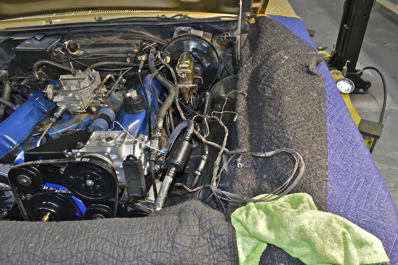
A little more work to this car. So the wiring harness needs to be replaced and when I say wiring harness I mean everything. But for now I was able to trim it back to sections of wire that didn't break when bent 180 sharply. This was near the booster. Since there aren't really any wiring harness I could find for the '68 with options (air con) I am going to temporarily mend this one as a stop gap measure to keep the car from burning itself to the ground.
I'm going to start with the main feed line bundle which includes the main B+ feed, the starter relay activate, "ALT" warning lamp, and ignition resistor bypass. I am going to delete the ignition resistor bypass wire as this is getting electronic ignition. Well technically it had electronic ignition originally, but then the crappy Pertronix died and I went back to a points distributor temporarily.
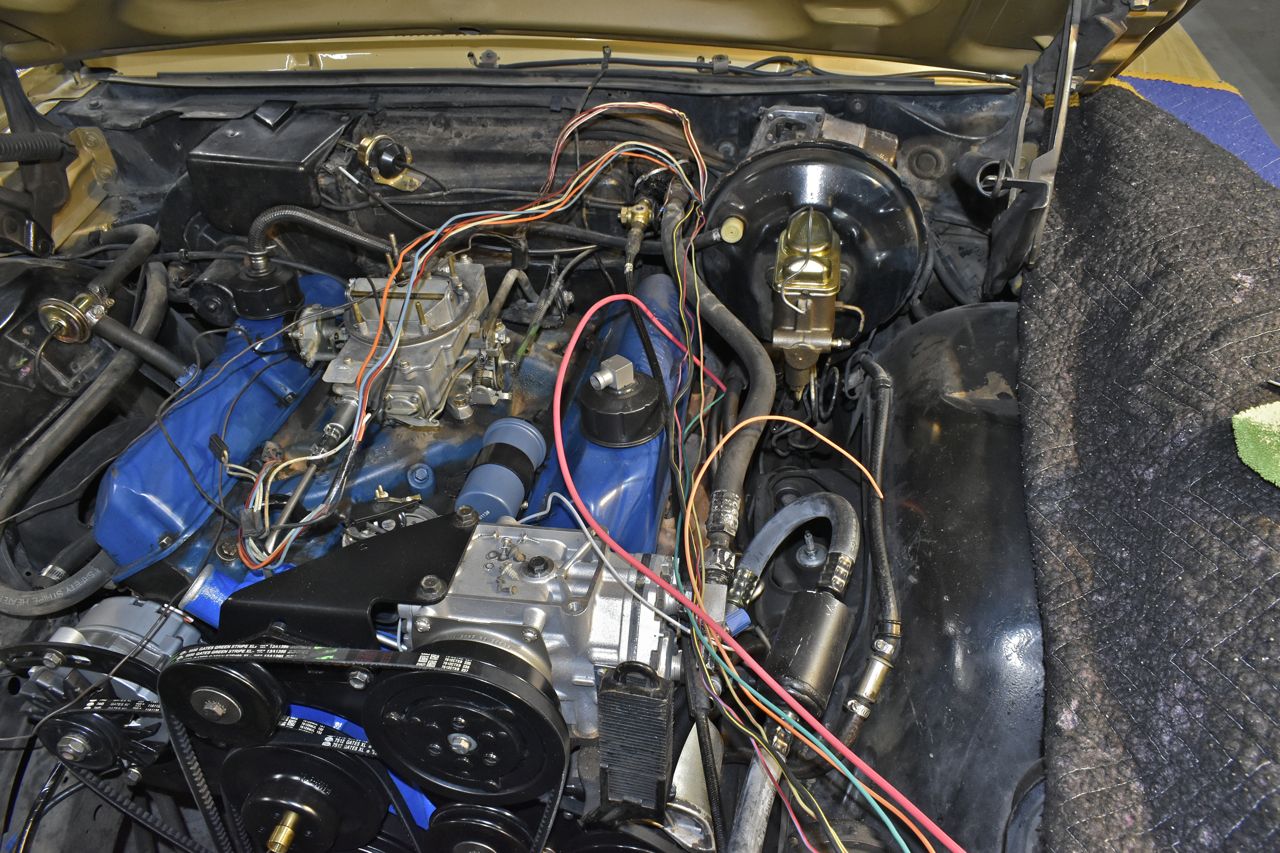
These large crimp sleeves come in handy for large gauge wire. After crimping I soldered them.

Then of course I used heat shrink.
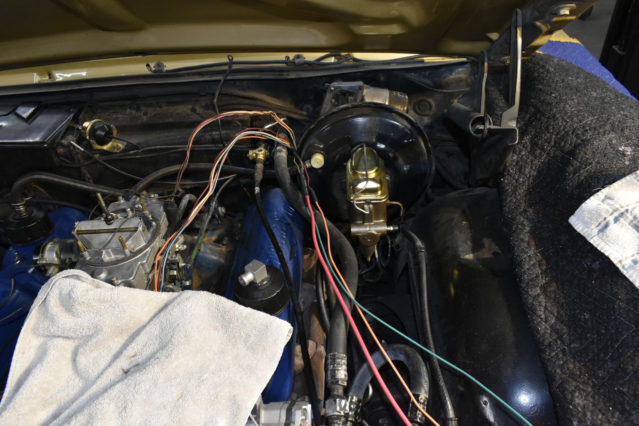
As a side note I straightened all the fins on the condenser.

That main feed, "ALT" lamp and starter wire were taped and run across the header over to the battery area.
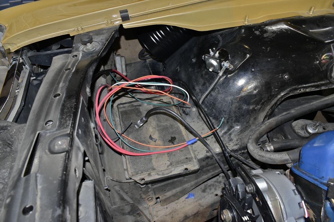
Since that wire bundle was run, I could put the radiator back in.
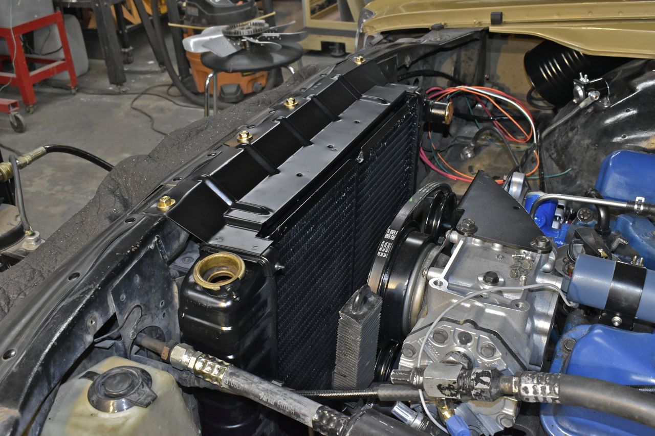
And the fan, shroud and then tighten the V belts.
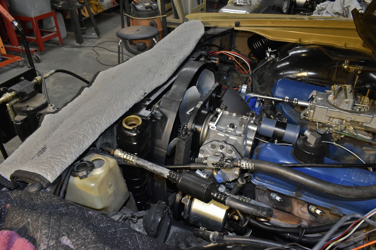
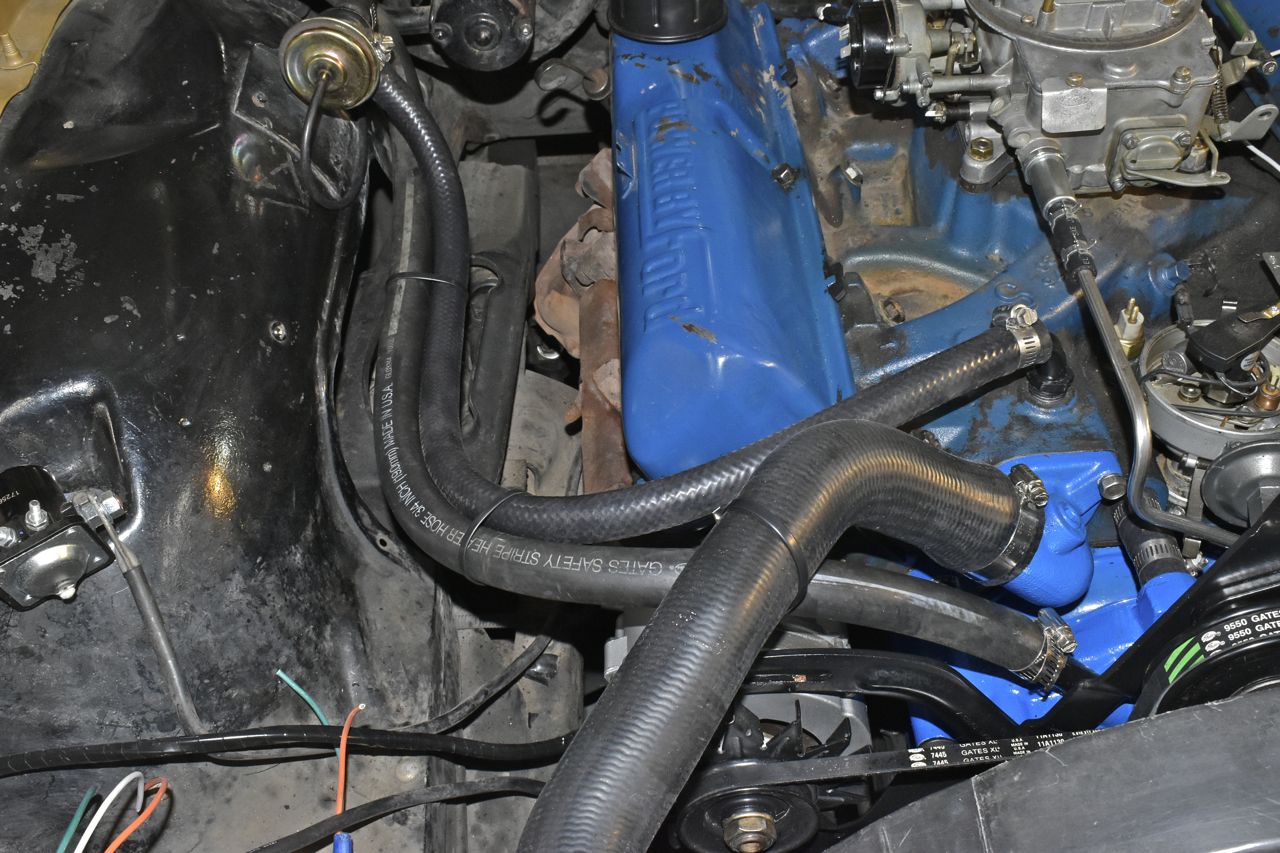
Now for the heater hoses I needed something to keep them together and suspended for a bit. I hate plastic zip ties, but until I change the heater core and remaining two hoses of which I'll use Adel clamps to support them I decided on a stainless zip tie. But to keep the sharp edge of the stainless from cutting into the hoses over time I used industrial grade PVC heat shrink. That stuff is really tough.
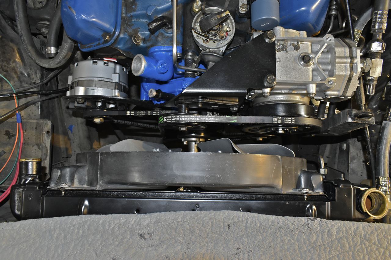
Now you have to measure your loop before hand and cut the PVC to the correct length then heat shrink.
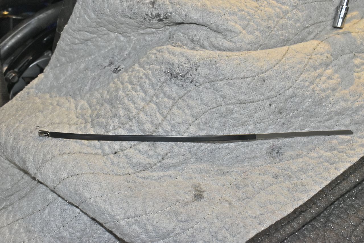
Once you do that, fold over once to help lock it in place then fold the edge squarely over and crimp tightly with pliers. This rounds off the edge and you won't cut yourself on it. Unlike those crappy plastic ones.
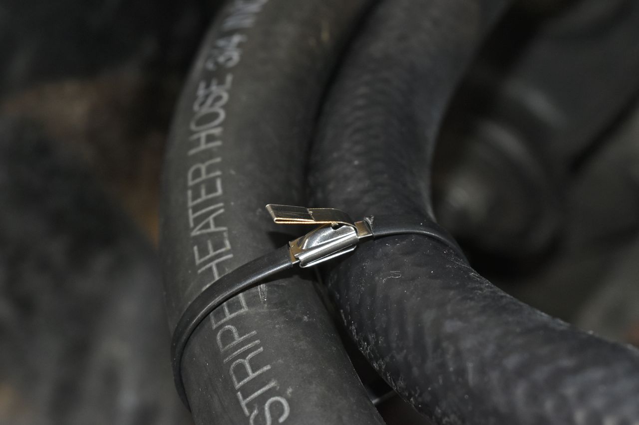
For a zip tie it's not to bad like this. Being stainless it'll resist corrosion mostly and it will not harden and shatter like old cooked plastic zip ties (aka zap straps). They'll last a really long time.
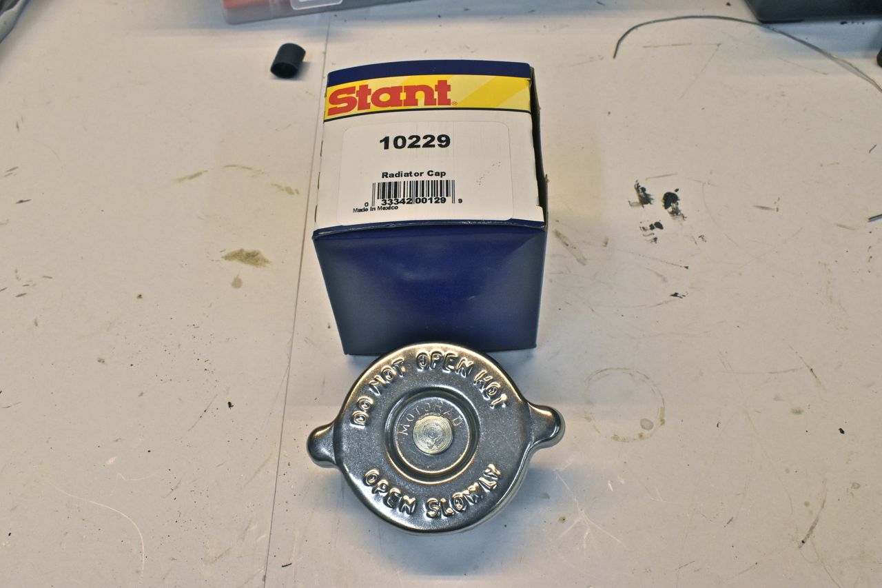
New radiator cap. I guess Stant bought out Motorad. I ordered three of these and they all are the same.
Overflow tube is connected. Just remember there is supposed to be no overflow tank. You simply do not fill the radiator up all the way. There is a mark on the tank to fill cold.
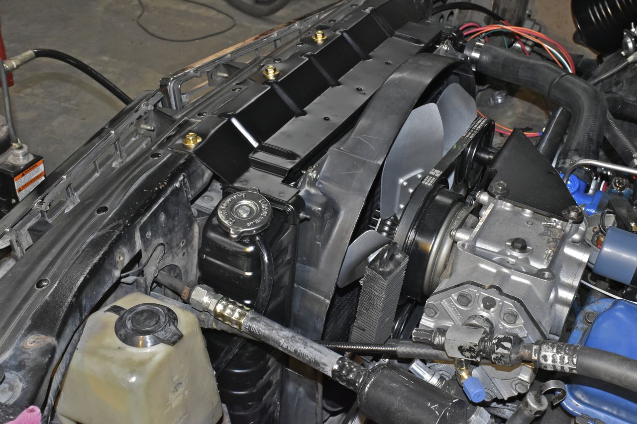
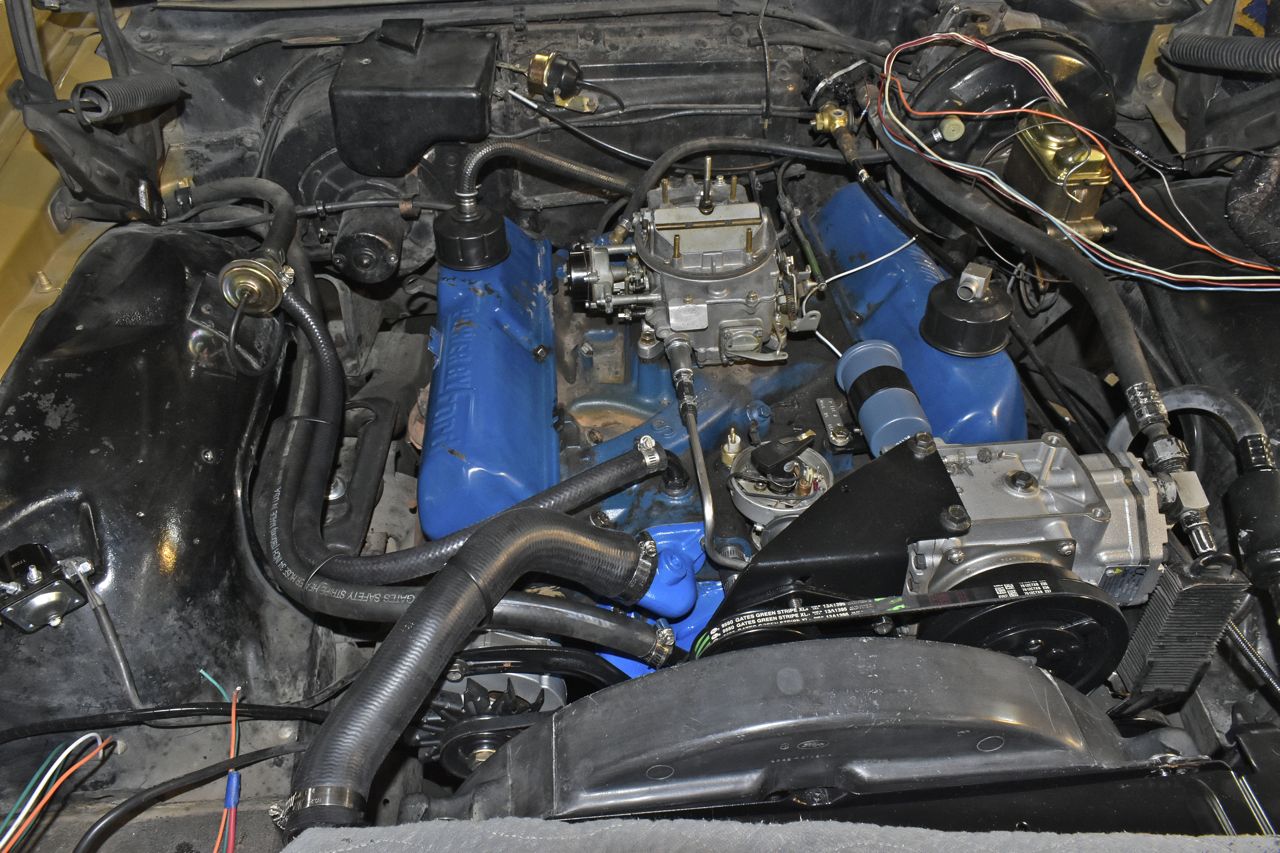
Slowly coming together.

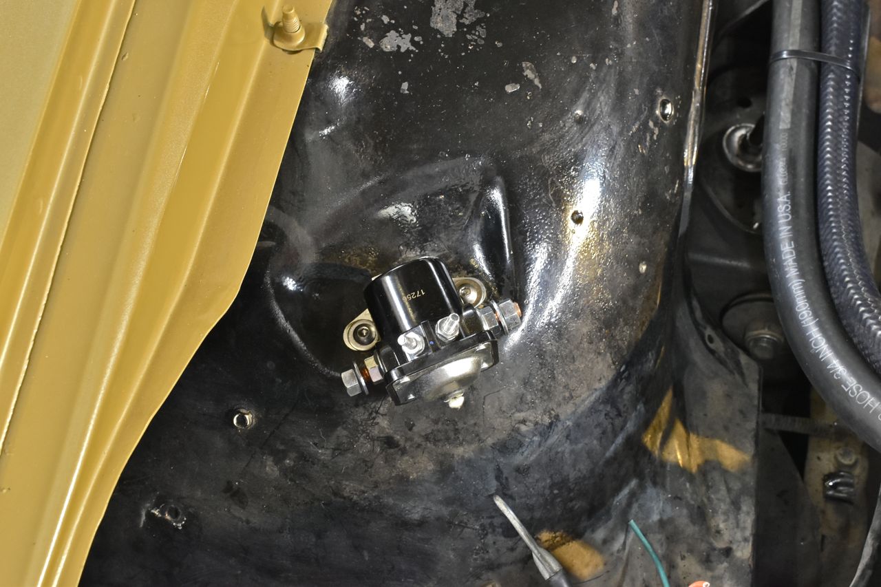
The sheet metal screws holding the starter relay down were stripped so this was loose. Well there's a potential no crank problem. I just drilled for 1/4 and used stainless nuts and screws.
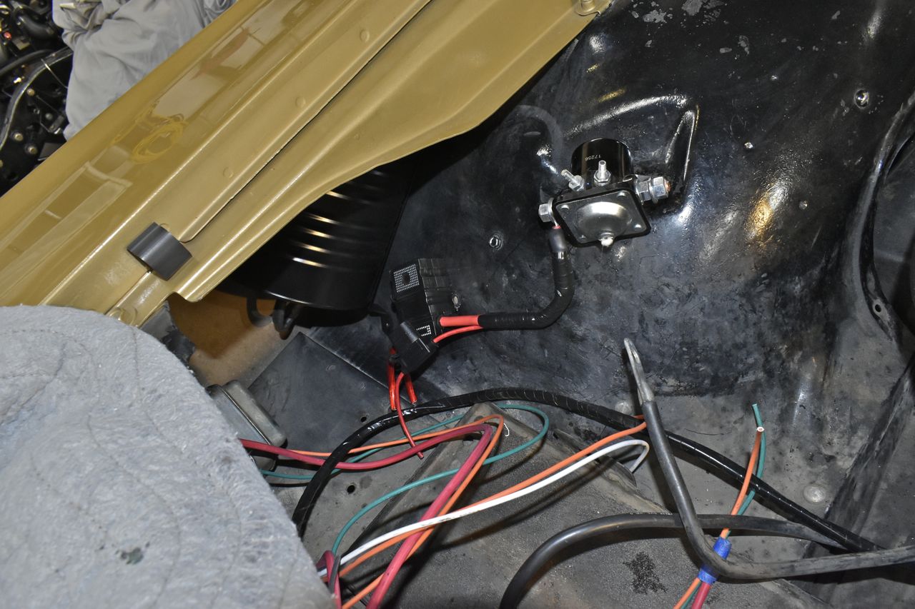
Here's my protection for basically the entire car. One 80 amp MAXI for the cabin feed (whole car), another 80 amp MAXI for the main charge lead from the alternator to the battery. Now even though the alternator is 60 amps, since these fuses are thermal and running a 60 amp fuse whilst pulling close to 60 amps on a hot day in a hot engine compartment can make it open. So whilst 80 is more than ideally the alternator can put out, it will protect against reversed battery leads or a reversed jump start as when reversed the bridge in the alternator will act like a short and the 80 amp fuse should pop before the individuals diodes in the alternator do.
The smaller ATO is a 7.5 amp for the voltage regulator and field current.

This is slowly coming together. However I noticed the starter main feed isn't supported by the clamp normally under the exhaust manifold.
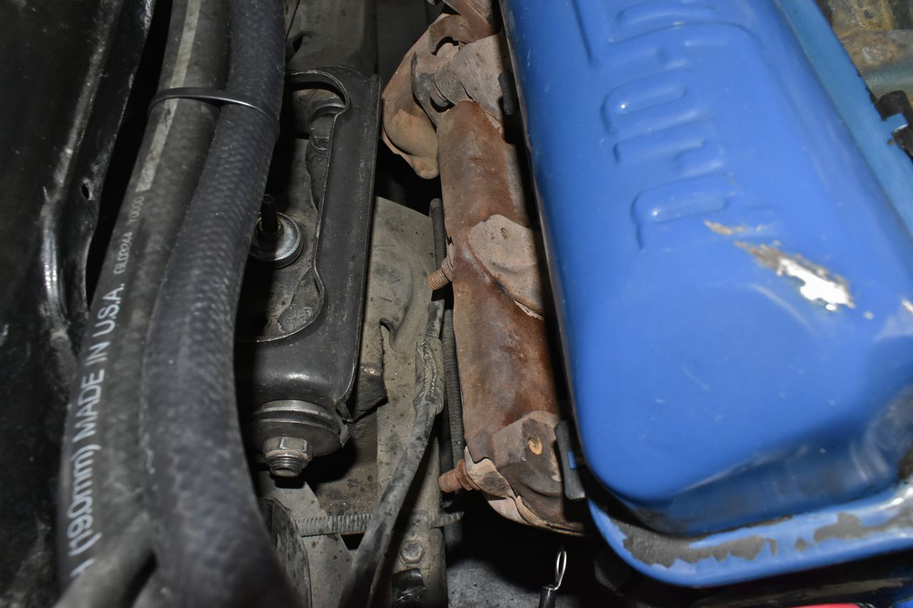
Yup, that starter lead is just floating around between a moving control arm and a hot manifold. More crappy bodge jobs to come.
