1968 Ford XL Repairing Whilst Keeping It Roadworthy : 36 FE Engine DIY Valve Job
2023, November 14
1 - 2 - 3 - 4 - 5 - 6 - 7 - 8 - 9 - 10 - 11 - 12 - 13 - 14 - 15 - 16 - 17 - 18 - 19 - 20 - 21 - 22 - 23 - 24 - 25 - 26 - 27 - 28 - 29 - 30 - 31 - 32 - 33 - 34 - 35 - 36 - 37 - 38 - 39 - 40 - 41 - 42 - 43 - 44 - 45 - 46 - 47 - 48 - 49 - 50 - 51 - 52 - 53 - 54 - 55 - 56 - 57 - 58 - 59 - 60 - 61 - 62 - 63 - 64 - 65 - 66 - 67 - 68 - 69 - 70 - 71 - 72 - 73 - 74DIY Valve Job at Home
I would be remiss if I didn't state I had my reservations about doing this at home without a proper guide/seat machine. This challenged me to think pretty far out of the box to pull this off. With that out of the way, here's the story.
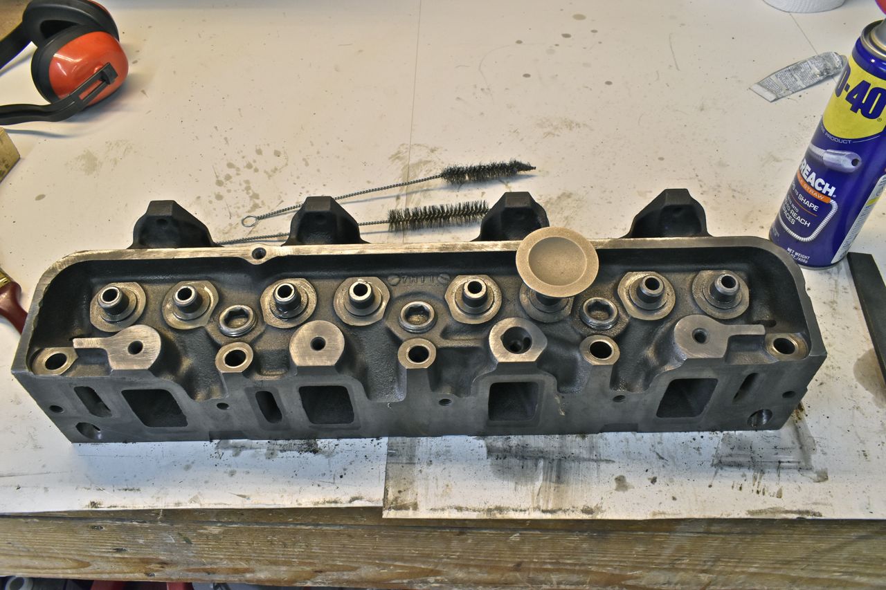
This is one of the nasty heads off that Z390.

This engine still has the lead deposits on the valves.

You can see the lead filled in the recess in the valve. I've had this with another FE and it would detonate like mad on modern fuel with this lead buildup that acts like a glow plug after a few minutes of running. There's no fuel additive like Berrymans B12 or Seafoam that will clean the lead off. The only way is to aggressively physically remove the deposits.

Since the vast majority of the guides were worn, they all needed to be replaced. I watched a few videos of machine shops performing guide replacement to get a sense of what's involved. Now for those unfamiliar with that process, the guide/seat machine floats the head then a round rod (basically a valve stem) is lowered from a mill type feed into the old head guide hole and this locates the head. The head is then locked into position and the round guide rod exchanged for the drill/reamer, then the old guide in the head is drilled and reamed oversize for a new false guide insert. Once that's drilled and cleaned an air hammer is used to install the guide into the head into the required depth. this is performed all from the top of the head.
In thinking about this I needed a way to centre the drill bit with respect to the seat and keep the bit at the 13˚ angle of which the FE valve train is located. All I have is a mill and lathe. After giving it some thought I came up with a plausible way to do this. First I needed the drill/reamer. This was pricy at 200 dollars shipped.
It's actually 3 in one. The top is the pilot, the next small section is the drill and the rest of the shank is the reamer.
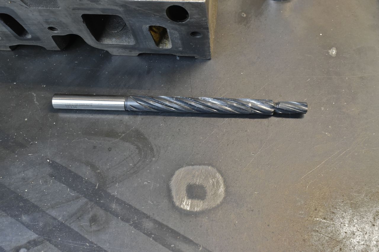
This makes a 0.500" bore hole in the existing guide hole. The false guide inserts are 0.502" so the 0.002" is the interference fit that holds them in place.
Next I made my own drill bit seat guides out of 6061-T6 aluminum on the lathe. I made one for the intake seat and one for the smaller exhaust seat.
This is the intake guide piece I made.

I whacked it out of this large chunk of aluminum.
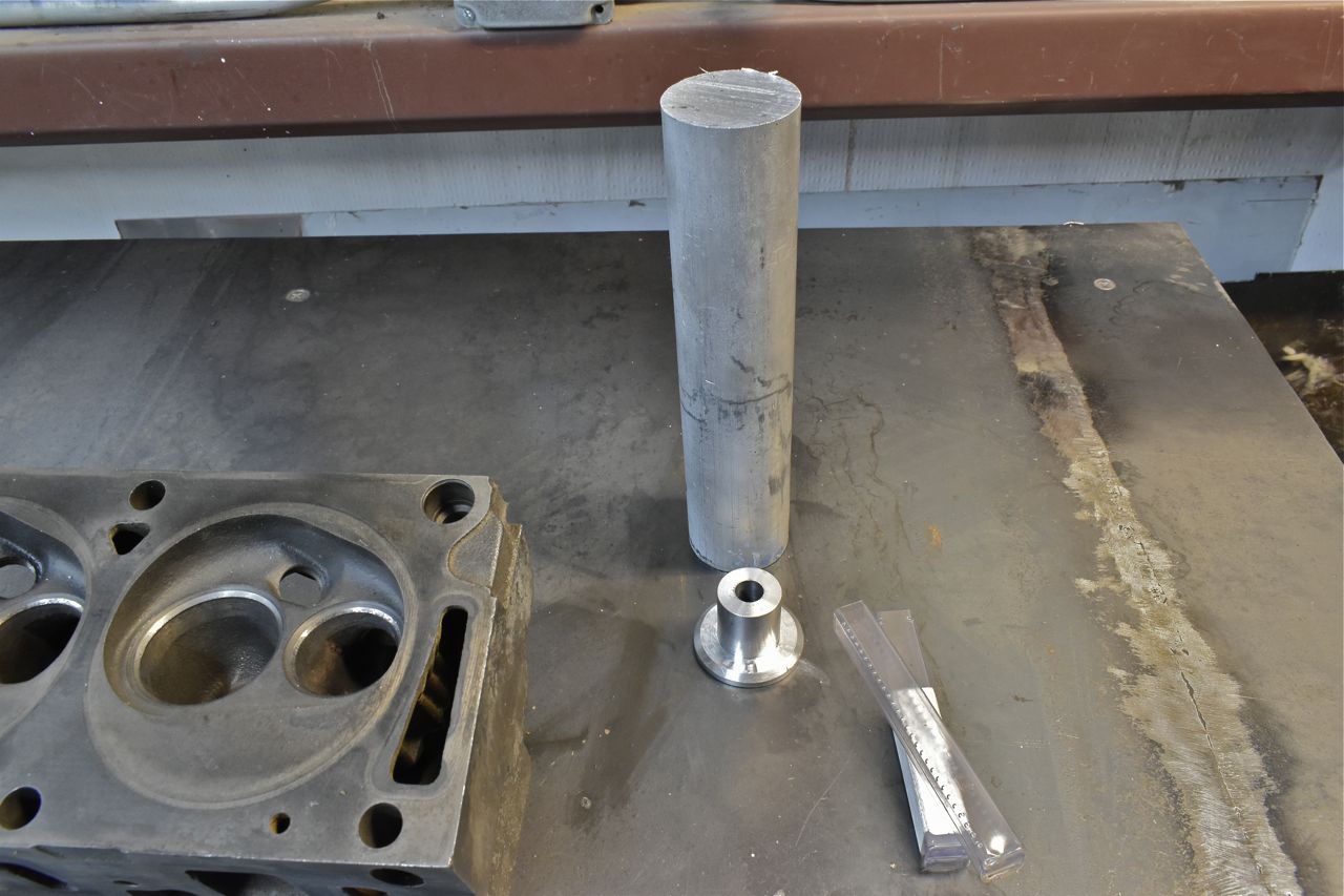
I will be drilling from this side like so. With the head flipped up-side-down the machined rocker arm side keeps the original guide holes perpendicular.

This is how it will work in the mill. Since my guide locates the drill I can leave the head float on the mill table and just press down on my aluminum guide as I drill.

This is the setup.


This is the exhaust drill bit locator. As you guessed it mimics the valve. The face on my aluminum locator is cut at 45˚ to match the valve face.

Now because I had the head on my mill table there wasn't enough room to finish the bore on the guide. I aligned the table on the mill to the pilot portion of the drill went into the 'T' slot on the table, but I had to finish the boring of each guide with a cordless drill on the bench. There was about 1/2" left to go, the majority of the reamer was already into the guide hole on the mill so it's pretty locked into place where drilling by hand wouldn't affect the results with careful attention.
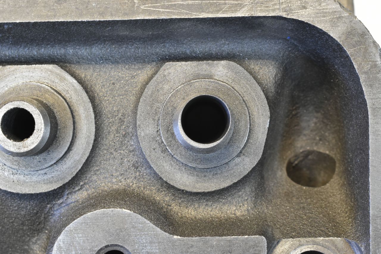
To install the guides I took a generic (Walmart) air hammer bit set and ended up making a square shoulder on it to drive the guide insert into the head.

You can see the shoulder in the bit above. After drilling I cleaned the holes, lubed them and installed the first guide. But then I had a problem. Because of the core shift in the head, the guide holes are not centre'd with the bosses sticking up and it cracked the side of a boss. So I chased that crack with a dremel and carbide bit so it wouldn't spread, then for the rest I opened up that boss protrusion in the head some with a porting kit so it wouldn't crack due to the thin wall when the false guide was pressed in with the air hammer.

I filed the tops of the guides to match the rest of the machined top surface.
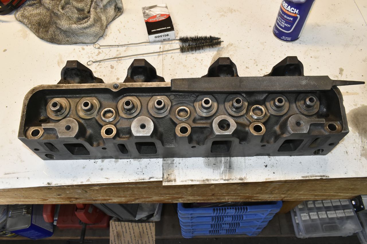
I had one brand new intake valve on hand so I used that as my guinea pig to test the guides. They all feel very good. No binding and not loose like the old ones.
I was curious how well my system worked, so I used that new valve to see how well it would lap to the seat. It took little effort for a smooth concentric lap. So my guide installation is right on the mark.

I did notice three oversized stem valves in these heads. Only these valves have the "FORD" logo on them. Was this a factory mistake, or was it worked on sometime long ago. Dunno. This is the first time I've seen oversized valve stems.

Whilst I was waiting for the new valves to arrive I wanted to install oil restrictors to the rockers. I've seen people use carburetor jets but they move about in the head and I wanted something fixed.
The oil passage in the head is 5/16" so this lends to just using 3/8"-16 tap.
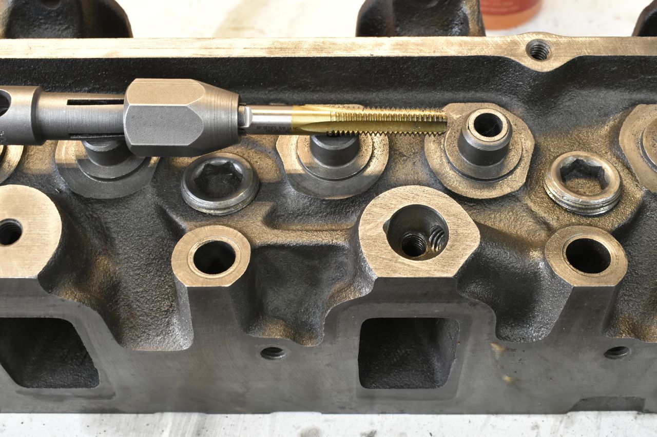
That's just a 3/8"-16 allen set screw with a hole in it.
