1968 Ford XL Repairing Whilst Keeping It Roadworthy : 33 Control Arms and Bushings
2023, November 14
1 - 2 - 3 - 4 - 5 - 6 - 7 - 8 - 9 - 10 - 11 - 12 - 13 - 14 - 15 - 16 - 17 - 18 - 19 - 20 - 21 - 22 - 23 - 24 - 25 - 26 - 27 - 28 - 29 - 30 - 31 - 32 - 33 - 34 - 35 - 36 - 37 - 38 - 39 - 40 - 41 - 42 - 43 - 44 - 45 - 46 - 47 - 48 - 49 - 50 - 51 - 52 - 53 - 54 - 55 - 56 - 57 - 58 - 59 - 60 - 61 - 62 - 63 - 64 - 65 - 66 - 67 - 68 - 69 - 70 - 71 - 72 - 73 - 74Here's a little more work on the XL.
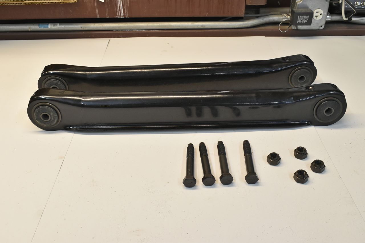
I looked in the Ford Master Parts catalogue and I could have sworn it said 65-68 lower rear control arms are the same. With that I used a spare '66 set to not have the car in pieces unnecessarily.

New bushings used.

Installed with hardware cleaned.

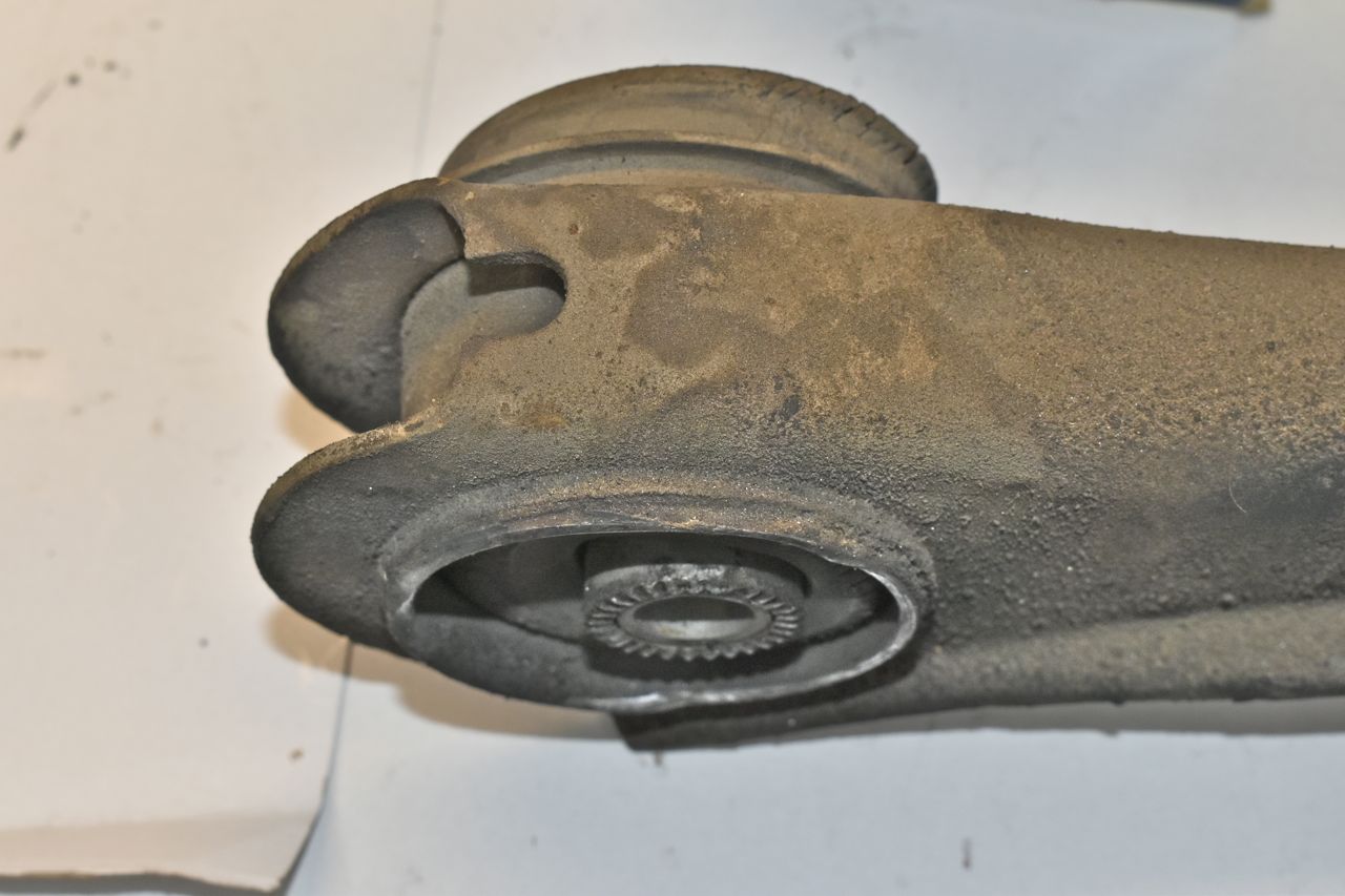
Here's the lower control arms off the '68. They are a little different and they do have holes drilled for a cable clamp. So they are technically interchangeable but you need to drill a hole and they look a little different. The odd thing with the control arms off the '68 XL is one has noticeably different bushings and yellow paint on it. The yellow painted arm has FoMoCo bushings but they are still in good shape. However the other arm has bushings that are completely hard and compressed. You can slide out the inner sleeve with your finger on both of those bushings. This was one reason the car would yaw very noticeably when throttle was applied.

I didn't have a spare rear upper for the '68. So this is the upper out of the '68 XL on the bottom. The top one is the '65/'66 one. Ford changed it in '67 for bigger bushings for more load handling. You can use a '65/'66 in a '67/'68 but not the reverse because the frame pocket in the '65/'66 will not accept the '67/'68 for its full range of travel.

So the upper control arm bushings were blasted too on the '68 XL.

This side was just gouging into the frame.

New upper control arm bushings.

Bushings are installed and hardware cleaned and prepped.

Now I did set the pinion angle as well. What I did is before I lifted the car I measured where I wanted the rear tyres with respect to the top of the wheel arch. Then with the car in the air and the springs removed I jacked up the axle until it was at the ride height I desired for the back and removed the propshaft. Then I measured the angle of the tail shaft on the C6 using my best judgement of when the shaft was centre'd. Once I had the measurement I laid a flat piece of stock steel over the yoke on the pinion and with the yoke orientated on the vertical I adjust the cam bolt on the upper control arm till the angle matched that of the tail shaft on the C6. Then tighten every single bushing bolt.
Click here to continue to part 34