1968 Ford XL Repairing Whilst Keeping It Roadworthy : 27 HVAC Blower & Harness
2023, November 14
1 - 2 - 3 - 4 - 5 - 6 - 7 - 8 - 9 - 10 - 11 - 12 - 13 - 14 - 15 - 16 - 17 - 18 - 19 - 20 - 21 - 22 - 23 - 24 - 25 - 26 - 27 - 28 - 29 - 30 - 31 - 32 - 33 - 34 - 35 - 36 - 37 - 38 - 39 - 40 - 41 - 42 - 43 - 44 - 45 - 46 - 47 - 48 - 49 - 50 - 51 - 52 - 53 - 54 - 55 - 56 - 57 - 58 - 59 - 60 - 61 - 62 - 63 - 64 - 65 - 66 - 67 - 68 - 69 - 70 - 71 - 72 - 73 - 74Cut the commutator down to a smooth flat surface. The brushes really did a number on it.

Installed the brush assembly and lubed the front bushing.

Assembled the brushes.
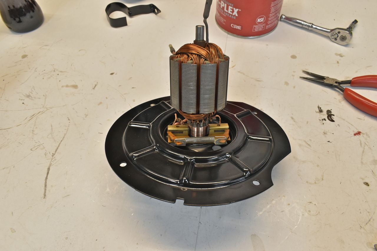
I tested this with no blower wheel and it spun up very fast and had a good wind down. Much easier to turn by hand now.
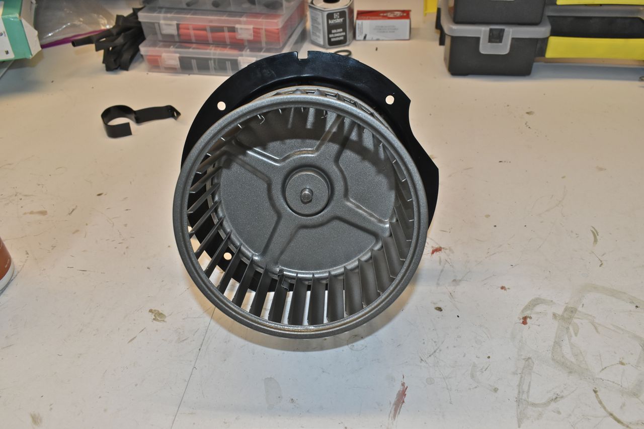
Cleaned and painted the blower wheel as well.
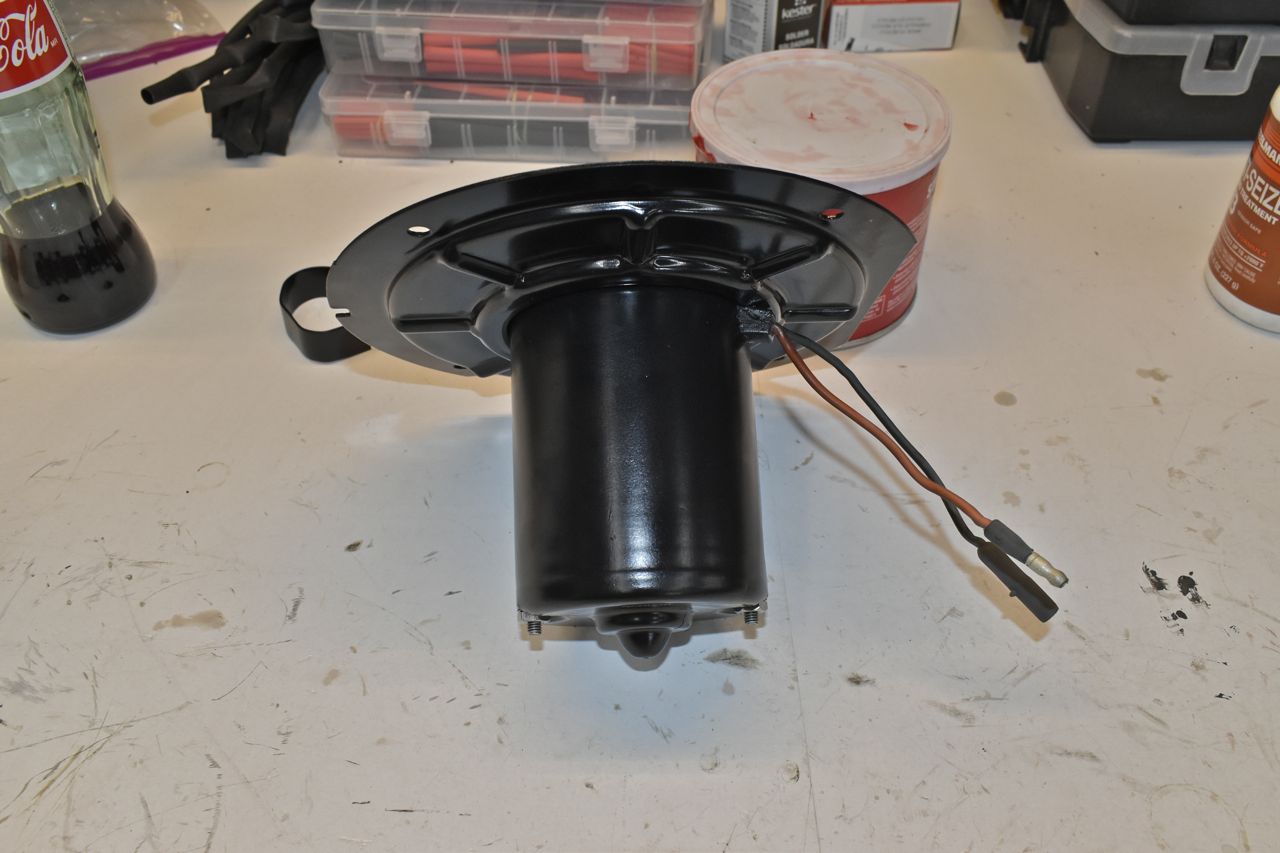
The motor cooling hose was in surprisingly good shape. Very pliable.


Before putting all this back on I cleaned all the lint and other debris out of the plenum. Now I can wire this up.

I reused all the connectors except the single post one. That was partially melted and then shattered into a million pieces trying to get it off the blower resistor. For new terminals I bought Packard/Delphi type 56 terminals. They click into the these housings.

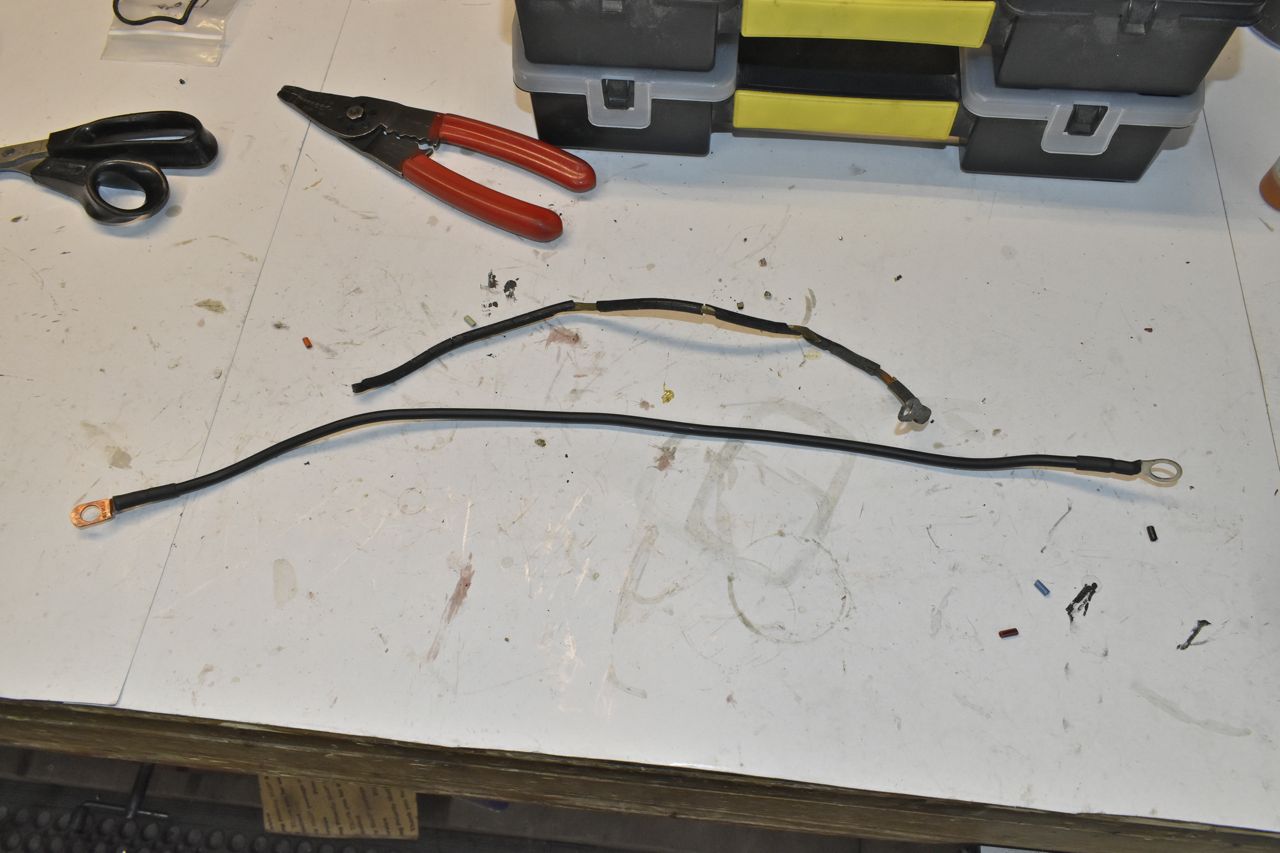
Shown is the old and new body to engine ground. I think you can tell which is the old one. I did change the location of the body ground to the stud and nut for the brake lever assembly. It's a much tighter bond than a sheet metal screw.
I finished up the HVAC and did the engine harness as well. I connected the "HOT', "COLD" and "OIL" lamps up and now they all work. I verified operation of the "HOT" lamp wiring at the connector as the "HOT" lamp may illuminate when cranking but that's just proves the bulb out, it does not prove the wiring, connector or sender. And that's the sender I did the temperature testing on, so I know when the "COLD" lamps goes out and when the "HOT" lamps lights temperature wise. But now I have an "OIL" lamp that works as it was inoperative.
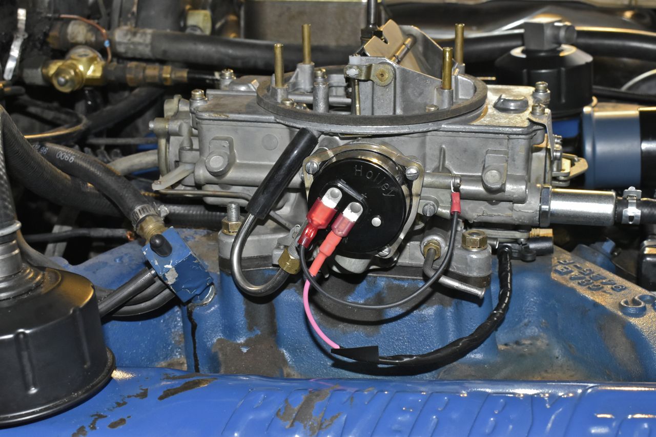
For the ignition feed, I went under the dash and painstakingly disconnected the resistance wire and bypassed it with a 15 amp inline fuse to the ignition switch. Now the coil gets full B+. I also tapped off this with a 3 amp ATO fuse for the electric choke.
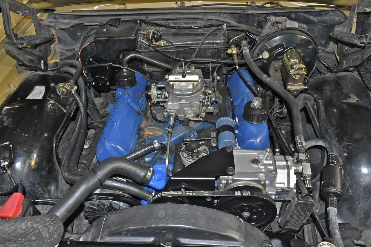
I also made a stainless loop to connect the choke pull off air sample to the air horn fitting so it can draw filtered air in and not clog up the choke pull off. I also made a little nipple fitting for the ported vacuum.
