1966 Ford LTD Resto-Mod : 025 Custom AN Hose Making
2023, November 14
1 - 2 - 3 - 4 - 5 - 6 - 7 - 8 - 9 - 10 - 11 - 12 - 13 - 14 - 15 - 16 - 17 - 18 - 19 - 20 - 21 - 22 - 23 - 24 - 25 - 26 - 27 - 28 - 29 - 30 - 31 - 32 - 33 - 34 - 35 - 36 - 37 - 38 - 39 - 40 - 41 - 42 - 43 - 44 - 45 - 46 - 47 - 48 - 49 - 50 - 51 - 52 - 53 - 54 - 55 - 56 - 57 - 58 - 59 - 60 - 61 - 62 - 63 - 64 - 65The next bit to tackle was the rear axle vent. The original piece is a cheap pressed in fitting to the banjo housing of the axle and the hose was a molded hose of which pretty much fell apart.
Whilst the axle was in pieces during its R&R I drilled and tapped for 1/8 in NPT. I then could use a fitting to screw in to attach a hose.
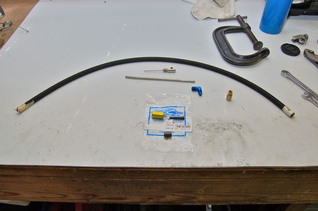
The brass piece is a restrictor and the blue angle fitting is a 3-AN to 1/8 in elbow.

The brass piece.

The original press in piece also was a restriction.
For the hose I had a piece of 3-AN Aeroquip 303 hose and fitting from an old airplane project so I thought I would use it up. I know it's overkill but it was just sitting around.
For those curious how to make a replacement hose for a certified plane or a custom hose for a homebuilt experimental, here's a quick snippet on installing the end fittings.

Fitting pieces

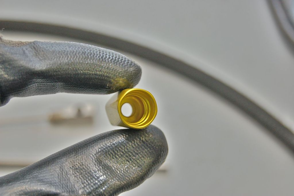
The collar has a left hand thread that grips onto the outside sheath of the hose.

First square off the hose end, usually tape and use a cut off wheel to do so.

Screw the collar on till it's seated.

To install the inside fitting, which incidentally has a right hand thread, you need an installation mandrel for that size fitting, in this case a 3-AN mandrel.

The tool screws in and locks inside the fitting.

With a bit of lubrication on the threads, push and screw the fitting in, it takes a bit of oomph to do so. The threads on the inner fitting engage in both the collar as well as inside the hose itself. Because those threads are right hand and the outer collar is left hand, it locks itself in place and cannot vibrate apart. This hose is also rated at 3000 psi working pressure, it can be used for oil, fuel or hydraulics.

Once it's seated, unscrew the mandrel.

Done.

Installed.

Next lines to be installed were the fuel and brake lines.
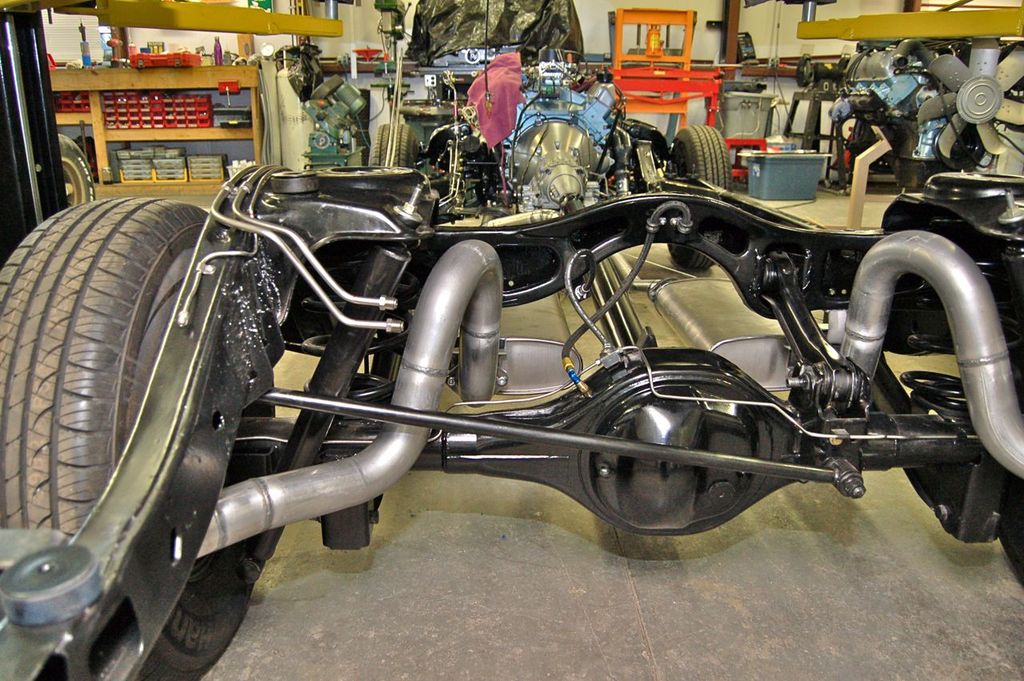
For the fuel I used 3/8 in stainless lines and the brakes were 3/16 in stainless lines as I never want to have to deal with corrosion on lines. For those wondering why there are two fuel lines and two brake lines running to back, which would be a good question, its because the extra fuel line will eventually be the return line for fuel injection and the extra brake line is for the eventual 4 wheel disc brakes with anti-lock and traction control. The extra lines are capped off for now.


In the interim I did add a dual circuit master cylinder instead of the single jam jar master. The shuttle valve was from a parts car so I cleaned and put new O-rings in it and had to add the residual pressure valves (pink cylinders) because the '67 master, which I used, does not have the RPV's built in as the '66 single jam jar did have one built in to it.

These are some other bits and bobs for the car. I wanted to see how the automotive grade AN fittings and hose were so I bought some for the fuel and high pressure power steering lines. I'll also be converting the car to power windows and locks, but later.

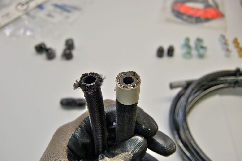
For comparison, on the left typical automotive grade 6-AN fuel/oil hose and aircraft 6 AN fuel/oil hose on the right.

On the left is the high pressure power steering hose and again the aircraft grade on the right for comparison.

These are the hose fittings for automotive use. These are Fragola hose and hose ends and they require no special tools. The fitting on the left is the low pressure fuel/oil fitting and the right fitting is the high pressure fitting (PS hose). These are much easier to assemble than the aircraft grade. I can see why they are appealing for automotive use.

Here's the finished hose end. It's easy and attractive.

I ran the fuel lines on the top of the frame rail because the 3/8 in lines were too thick to run on the side. To check for room I lightly crumpled aluminum foil (typical food grade) and placed them over the frame and lowered the body onto the mounts on the chassis. I could then measure the crush and ascertain home much room I had and where to route the lines. There's a little offset in the middle for the seat belt bolt that protrudes down.

When routing the front lines I used this as a guide as it still had the inner wings/fenders and I could estimate where the lines would need to rest.
