1966 Ford LTD Resto-Mod : 040 Wiring
2023, November 14
1 - 2 - 3 - 4 - 5 - 6 - 7 - 8 - 9 - 10 - 11 - 12 - 13 - 14 - 15 - 16 - 17 - 18 - 19 - 20 - 21 - 22 - 23 - 24 - 25 - 26 - 27 - 28 - 29 - 30 - 31 - 32 - 33 - 34 - 35 - 36 - 37 - 38 - 39 - 40 - 41 - 42 - 43 - 44 - 45 - 46 - 47 - 48 - 49 - 50 - 51 - 52 - 53 - 54 - 55 - 56 - 57 - 58 - 59 - 60 - 61 - 62 - 63 - 64 - 65Some misc bits...
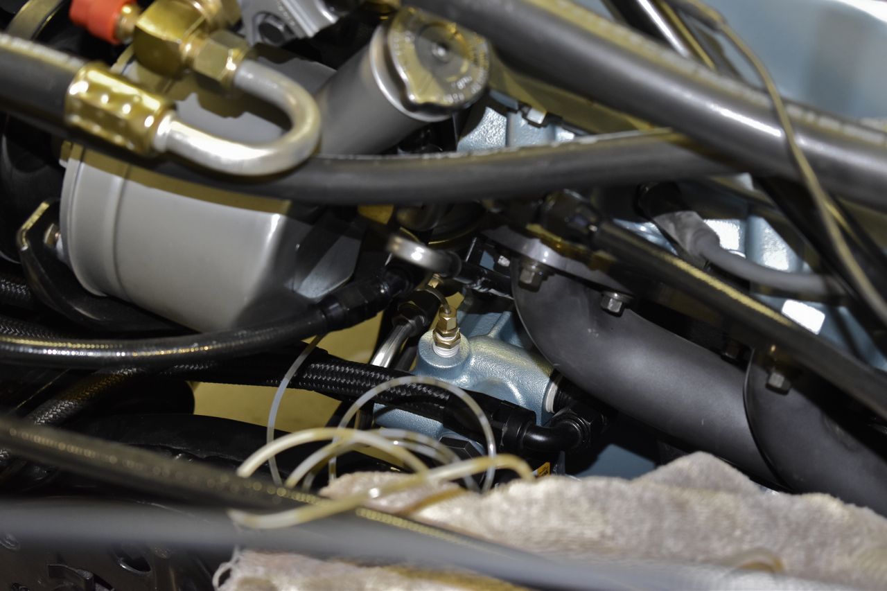
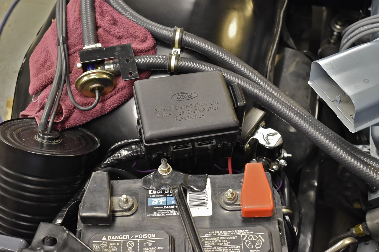
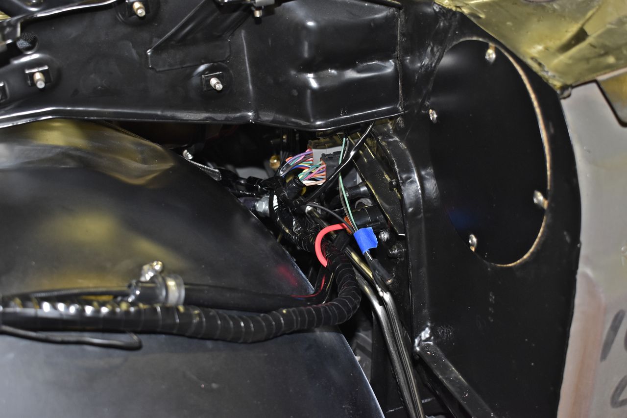
I had to make a back plate for the double hump line clamp as well as a standoff to secure the 2 fuels lines off the firewall.


On this picture you can also see the original firewall electrical connectors. These are going to be replaced.
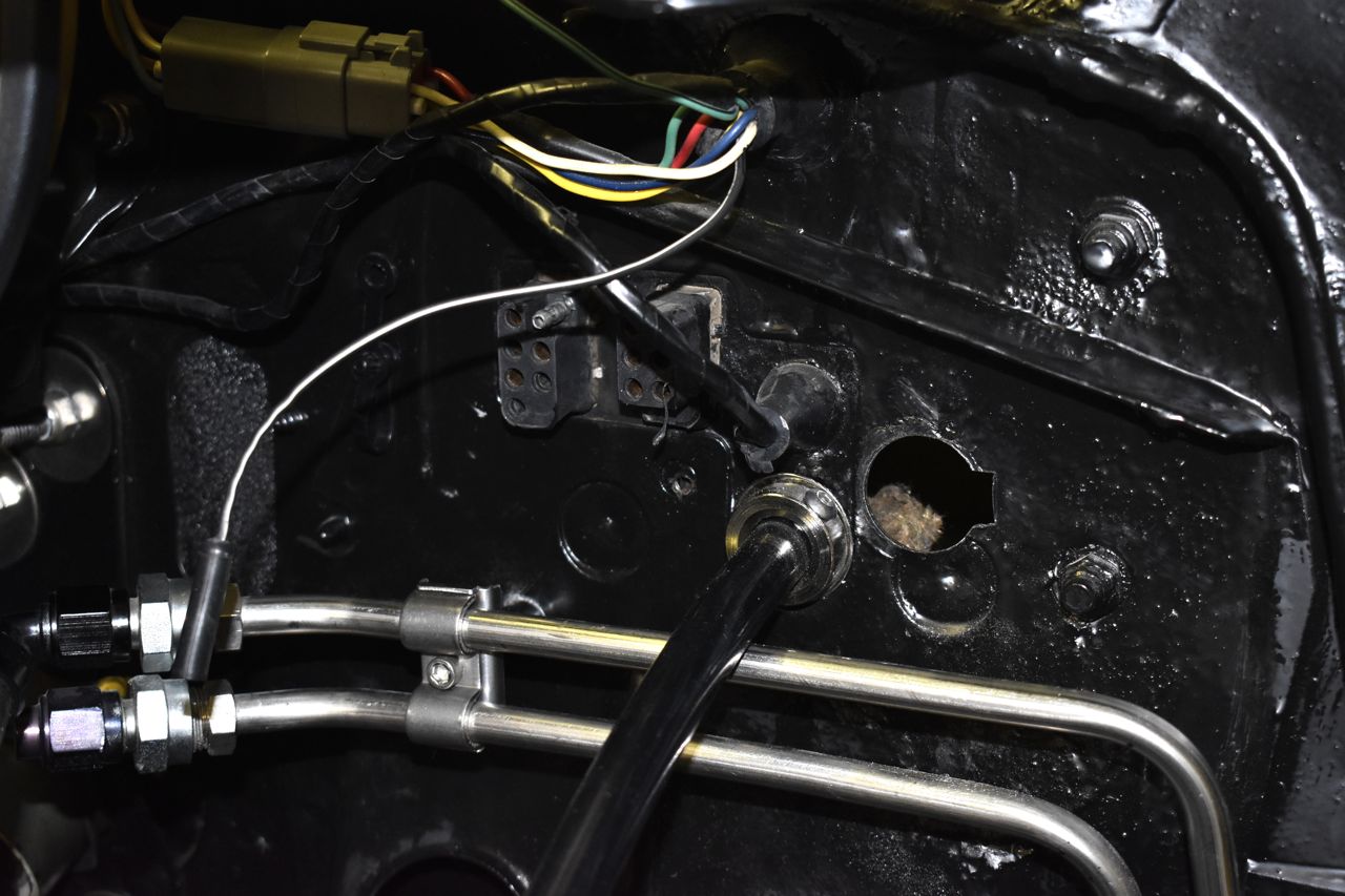
I was really lucky on bending up these lines. Instead of running on the body channel like the original poly tube did, these are clamped to the chassis all the way down, only here do they mount to the body.

They sit clear of any obstacles and do not vibrate on anything. Again really pure luck as I was estimating when I originally bent them.
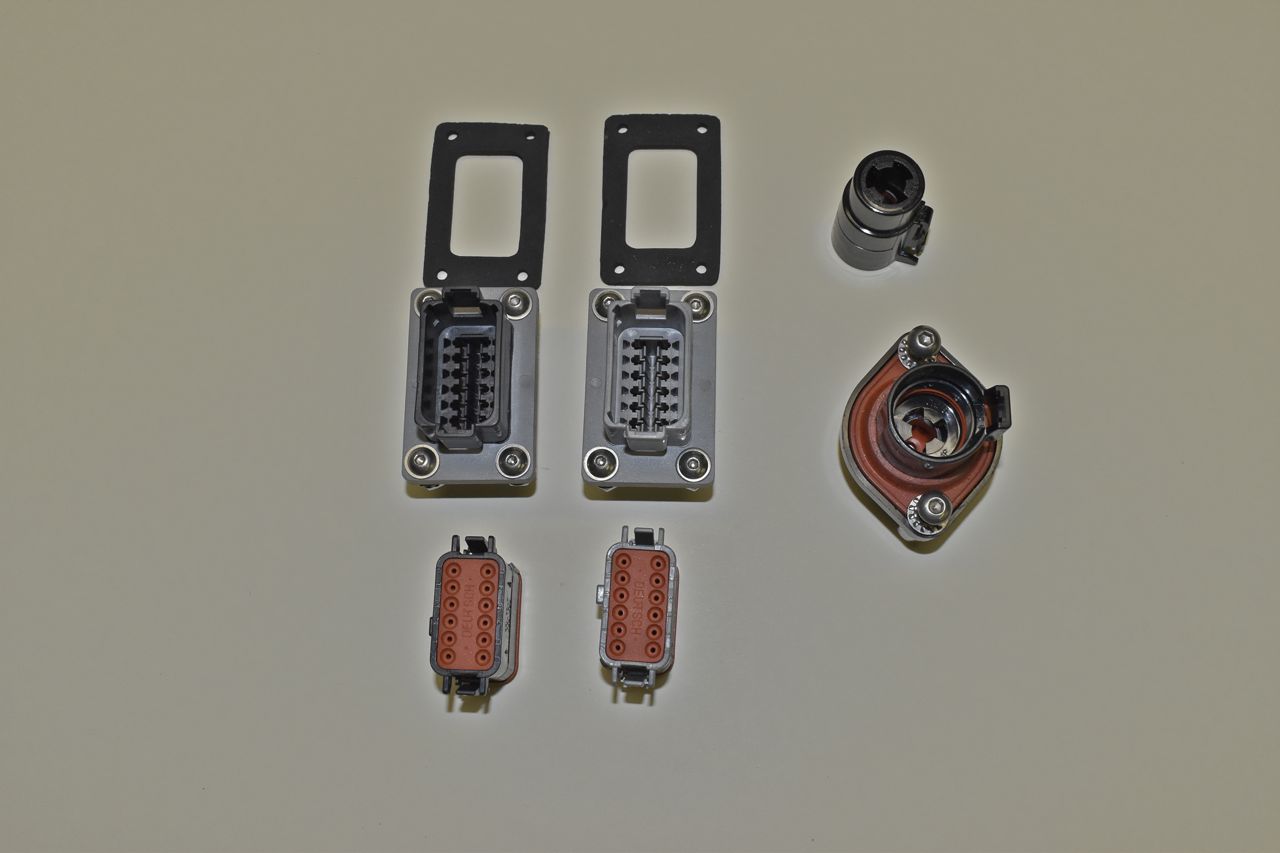
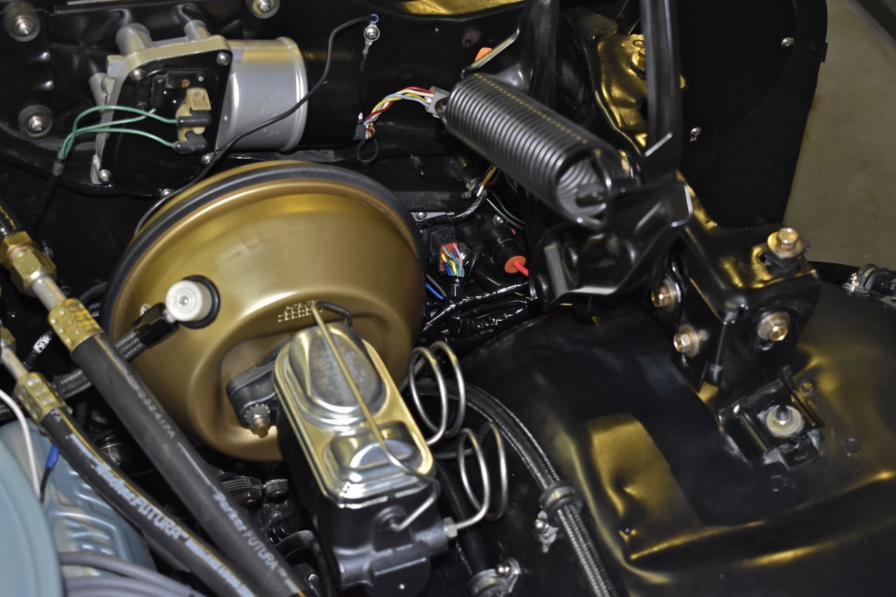
These are replacing the old Ford connectors.

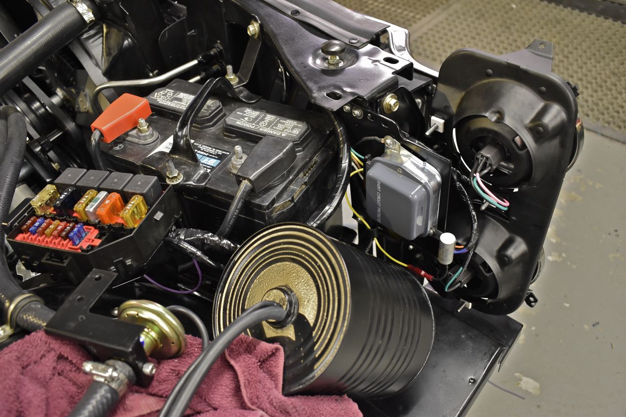
This is the new oil pressure switch and transducer.
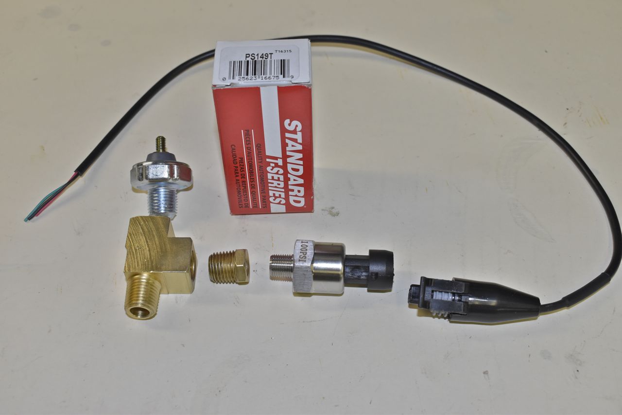
There is just enough room for them. I still had the mechanical gauge connected to the oil port.
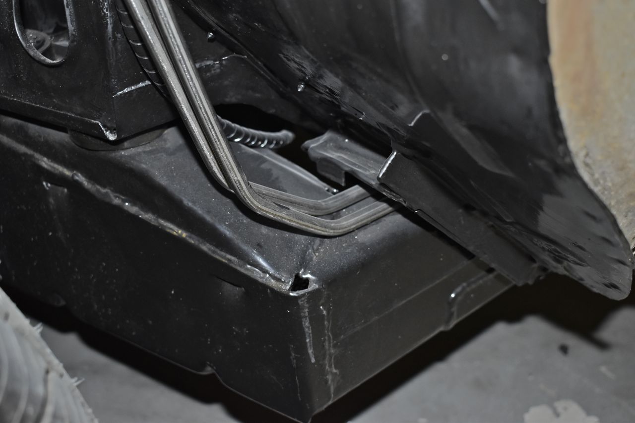
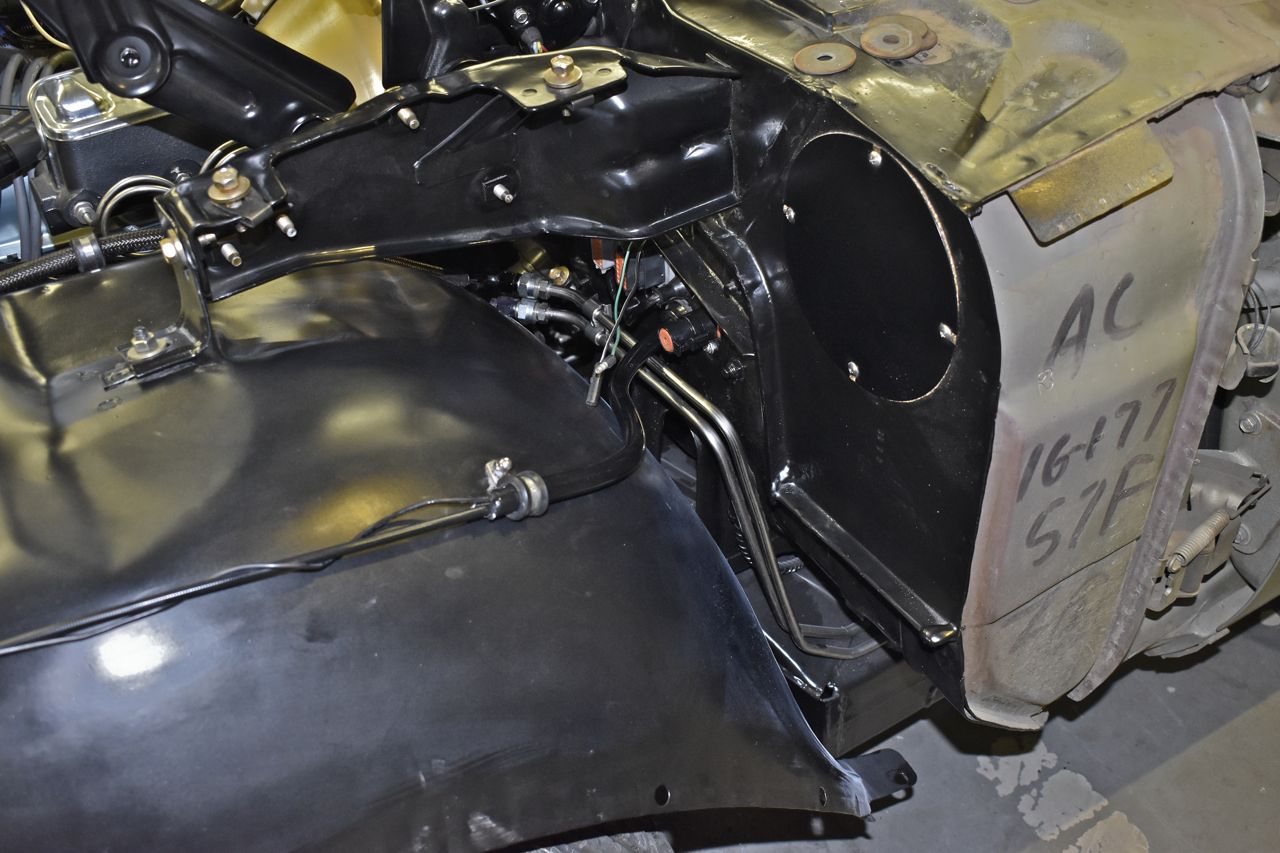
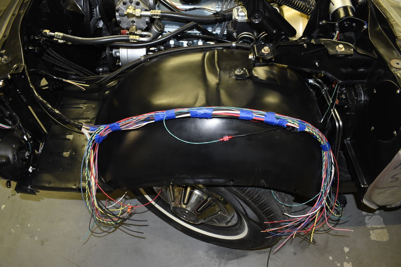
Finally installed the drivers side apron.
There's plenty of room for wiring, fuel lines and locking cable.
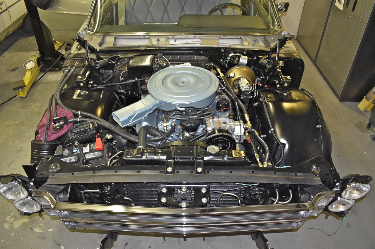
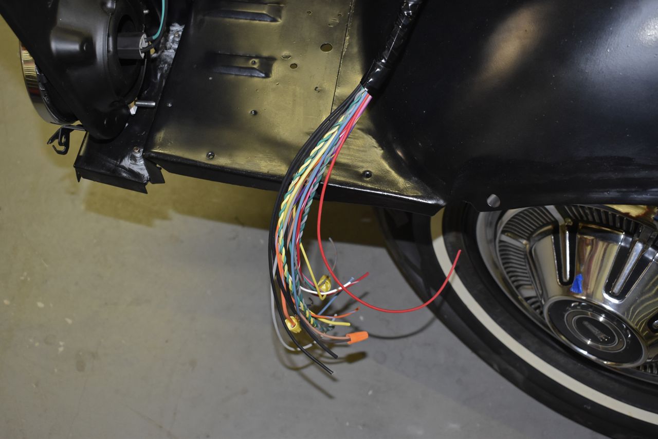
Laying out the first of 2 engine bay wiring harnesses.
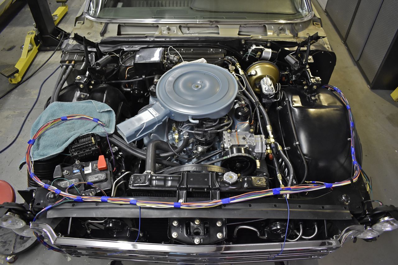
This one will get tucked under the radiator cross support brace upper channel. The engine management system will go on the front flat portion of the drivers side apron, hence the start of the multitude of wires dangling off that side.

That's pretty much for now.
Wiring, wiring, wiring....
I finished wiring in the Panther fuse box. For those who like the nitty gritty detail here's what's fused and on the relays.

Fuses/Circuit Breakers:
- 1. Alt output
- 2. Cabin main feed
- 3. Horns
- 4. High beams
- 5. Low beams
- 6. Engine management master fuse
- 7. Ignition system
- 8. Voltage regulator
- 9. Interior lamps (easier to change out here in the dark than under a cramped dash)
- 10. Engine management volatile memory
- 11. Fuel pump
- 12. Fuel injectors
- 13. Engine management master power
Relays:
- 1. Fuel pump
- 2. Engine management master power relay (turns on power to the control module, injectors and ignition)
- 3. Low beams
- 4. High beams
I will say one thing, putting the headlamps on the relays and using 14 gauge wire for them made a huge difference. When we originally bought the car I put brand new halogen bulbs I bought off of Rock Auto that was having a clearance on them. I think they were 2 or 3 bucks each. Anyway, on the old electrical system they were barely brighter than the old jaundice looking Ford stamped headlamp bulbs in the car. Now these halogens are really bright when the relay is triggered. Plus there is extra capacity the high beam circuit can handle up to 30 amps safely and if we want to we could use 100 watt high beam lamps in the lower headlamps for that country driving at night. Or even general aircraft landing lamps if they'll fit.
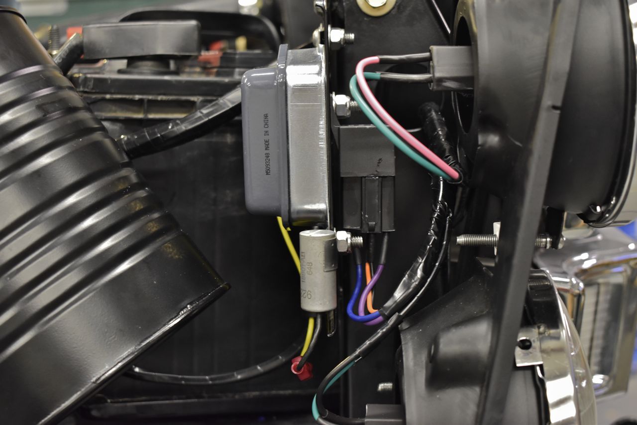
I put a newer RFI capacitor on the voltage regulator. The old original one was falling apart but weirdly wasn't leaky electrically and measured about 0.5 uF and was good to 450 volts. It just looked terrible. I couldn't find a repop version for the Ford, I found ones for GM that would work, but they started at 20 dollars. It wasn't good value for the application so I elected to use a 90's Panther RFI cap from the coil packs on the 4.6L. They come with two tangs so I removed one and it doesn't look to out of place.
Of course it really doesn't need it if I'm honest. The electronic voltage regulator has the free wheeling diode for the field. As a result it generates a tiny fraction of the spurious RF that the old mechanical point regulator did.
I ran out of relay spots in the fuse box so I elected to put the horn relay on the reverse side of the voltage regulator mounting plate. For those who are unfamiliar with these year gals, Ford runs the entire horn load through the steering column, through the brushes and through the contacts under the horn ring. Horns draw a decent amount of current, and not to mention they are inductive and when you release the horn ring the contacts arc and pit every time you use them.
Putting them on a relay alleviates all that, less forgetting the voltage drop they endure going through the column and steering wheel. I swear these same horns are several db louder on a relay.
The nice thing about the Panther fuse box is that it doesn't look terribly out of place in the engine compartment, plus the Ford logo is nice. The only out of place portion is the multilingual French embossing on the cover.
One last note I did slather dielectric grease on all the terminals to keep moisture out and prevent oxidation for long life.
However moving forward, here's some more pics.
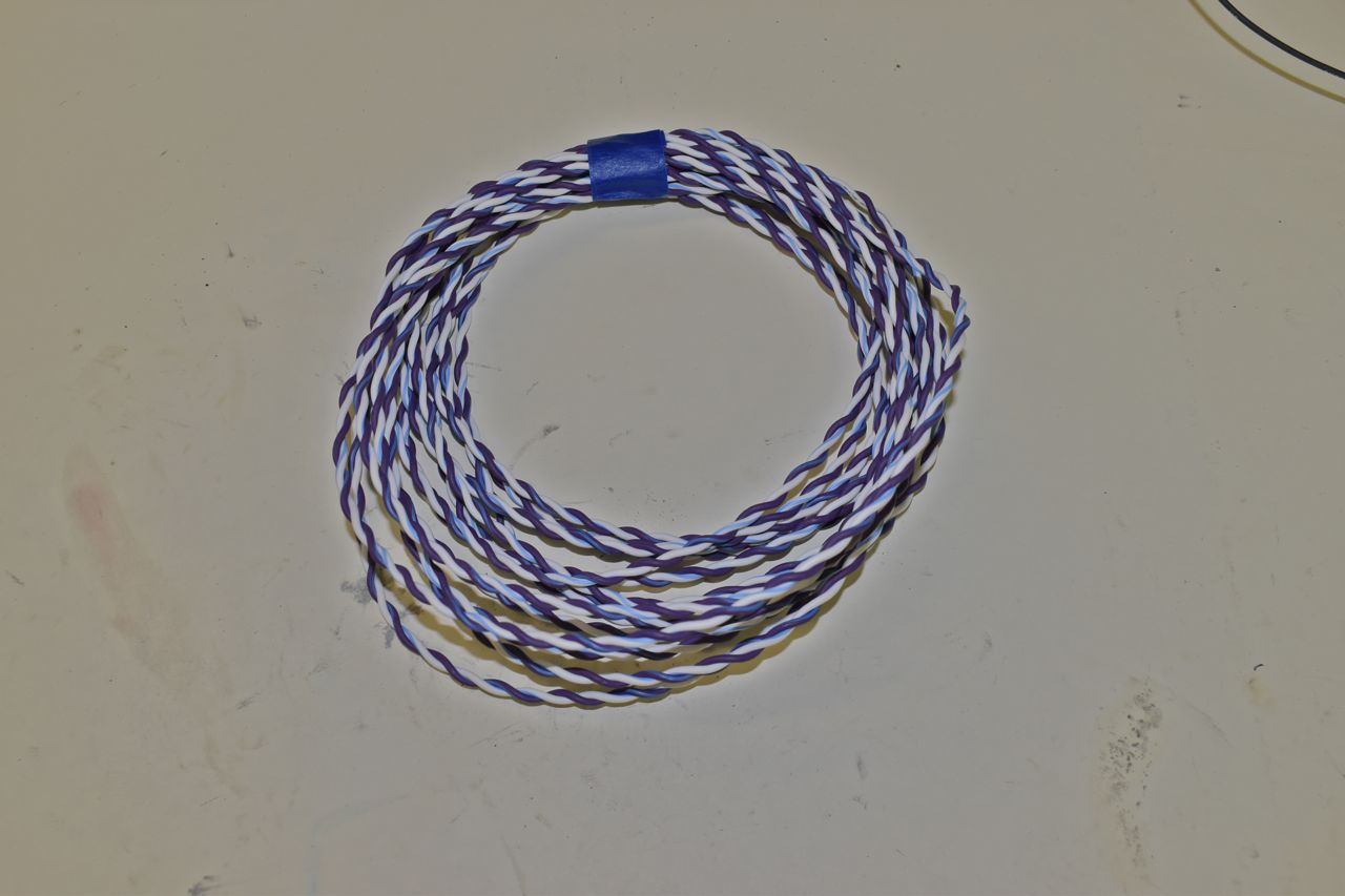
This is the last bit of wire needed for this harness.
They actually sell pre-twisted pair GXL wire. Of course you could twist your own in a drill chuck but since I had to buy more wire I just bought some pre-twizzled wire as well. This is for communications between the engine management system module and the interior convenience package module. I am also going to use this on the magnetic pulse generator (pick up) in the distributor to the engine management system module since it's long distance. One could also use this if they are using the Duraspark module in a relocated out of sight location as well.
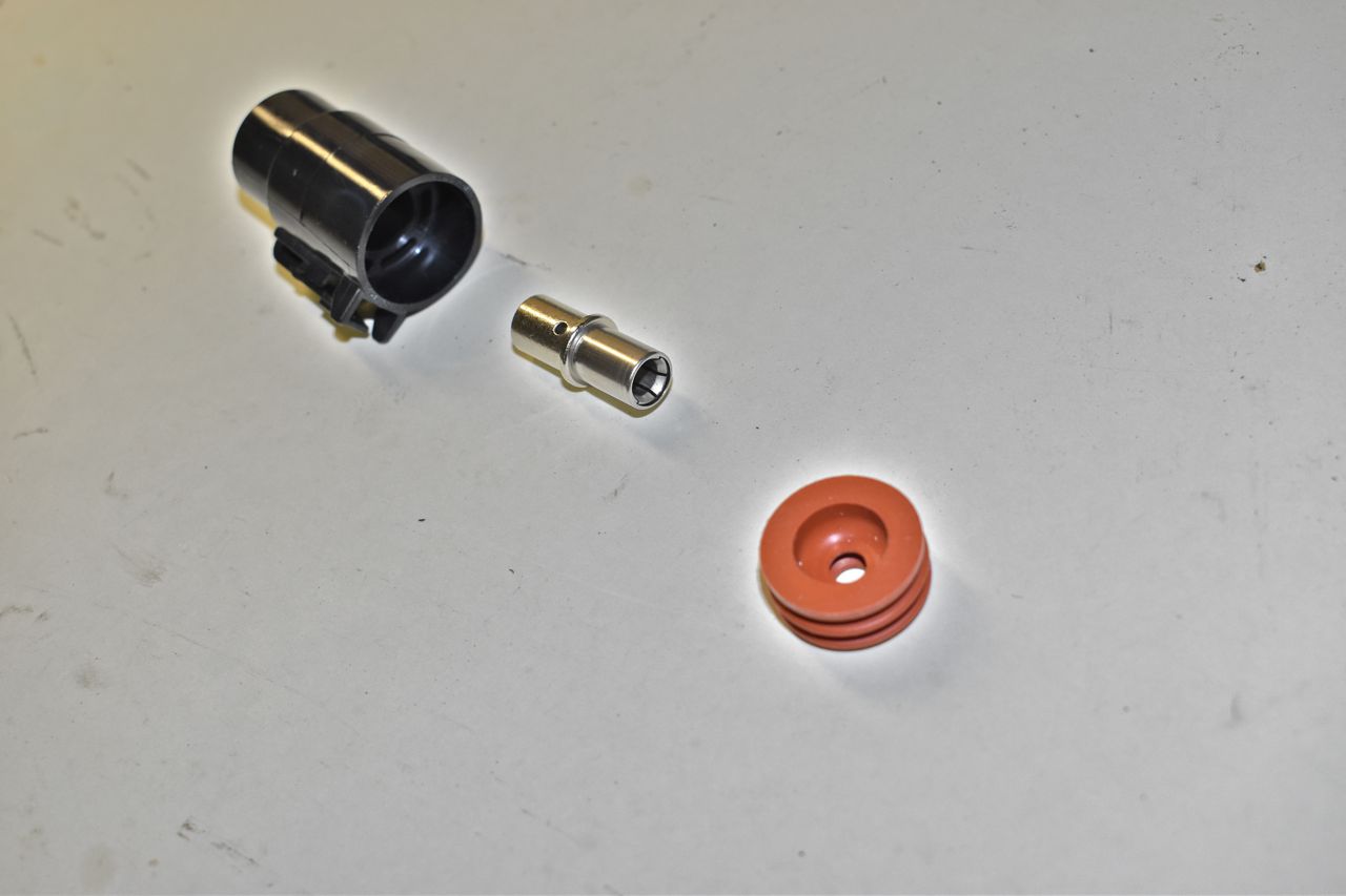
This is the high current feed connector from Deutsch. I'm using this for the main cabin feed. Ford just uses basically one bullet connector to supply the entire vehicle. If the car was loaded from the factory, I can see that melting, it's really pushing the limits on cheapness. This single connector can handle 100 amps continuous and takes up to 6 gauge. That terminal is meaty and does it bite into the mating terminal.
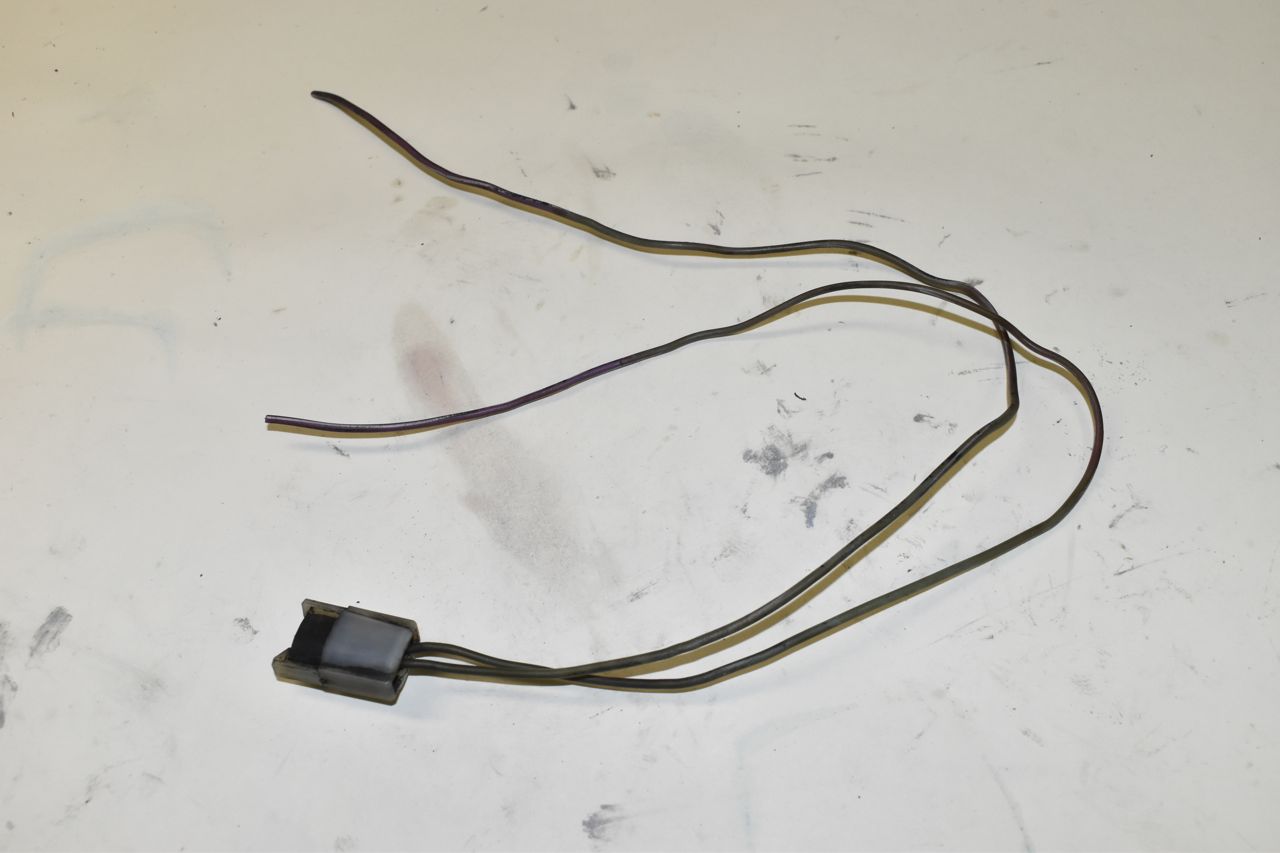
This is one of the few pieces I had to get used. I saw these repopped last year for 35 bucks I should have bought a couple, but they are gone now. This is the connector for the hydraulic brake failure warning switch on the shuttle valve. I got this off of my good friends pars car of a '71 Custom 500 sitting out in his back yard. I carefully removed the plastic locking cover and walnut blasted this, it came out rather nice looking.
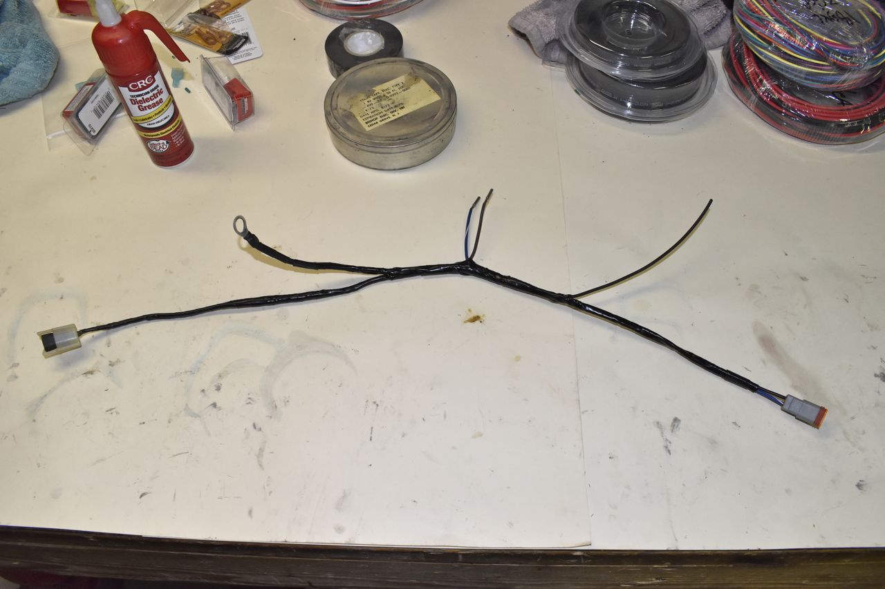
Here's a little sub harness. This also provides a connector for the bonnet lamp as well as a constant ground for the washer pump. I thought about this and to give options I thought I would include in a 3 pin connector both a continuous ground and the pulsed ground from the wiper motor to the washer pump. If I like the continuous action of the washer pump when I activate the washer switch I could leave it or if I want the pulsed action like the original I could move the pin in the connector housing for that option. I should mention I am using a Panther washer bottle with the integrated pump and low level sensor (Lincoln Town Car).
All the bulkhead/firewall connectors are populated now.
This is for later...
I also finished up little things like add the connectors for the front turn/running lamps. Although now that I'm looking at it I'll order these Deutsch connectors in black so they aren't so obtrusive looking.

I am taking a break from the engine compartment wiring, only one more harness to go which is the engine harness and all the transducers I've added to the engine and transmission, plus the ignition coil and distributor. Kind of getting tired of this part, so back to the doors and the power window and lock conversions as well as start on the audio system.
The plan for the audio system is this; (hopefully I can pull this off) I bought from a really nice member an original AM/FM radio for the '65/'66 and a dealer reverberation kit. However I want to go a couple steps further. First on the radio, it was stated it doesn't work, I haven't bench tested it yet. However it's a factory service part and I don't think it's ever been installed in a vehicle as a result it's really clean. The other fun fact about the '65/'66 AM-FM radio is that it's monaural only on both AM (obviously) and FM too. I need to see if the IF (Intermediate Frequency stage) in the FM portion is wide enough to allow the L-R portion through that is AM modulated so I can run a stereo demultiplexer in it. If not then I need to modify the radio to make that happen.
I also found on E-Bay just the reverberation tank portion for really cheap. So now I have two of the same reverb tanks.The plan is to basically just use the old school reverb tanks with modified electronics to add in a controlled amount of reverb via a dash control to both L and R channels. Now I'm not going to use the extra foot pedal and wiring harness. I have my own ideas on how to better this original application. I also intend on using external equalizers (front and rear speakers) and a 4 way amp mounted surreptitiously in the boot of the car (out of sight).
The reason why I'm pursuing the old school reverb tanks is we have a large console 1962 Grundig stereo in the house (model SO-390).
Here's a link for those who like antique electronics sort of this, we have this exact same one as this. SO390 Rüster Radio Grundig Radio-Vertrieb, RVF, Radiowerke
I R&R'd it a long while back and it came fully loaded with the FM stereo demultiplexor and reverb tank. It has a front panel control for how much reverb you wish and that old crock of a stereo sounds better than anything else I own. Granted it's not terribly powerful but it's the quality of the sound that is so warm and inviting. It's auditory nectar
So I thought it would be novel to have this is the LTD.
So all of that is next up after the doors are done. Basically I want the interior of the car to look as if it came from Ford that way. So no modern analog gauges or radios or cutting holes in the dash.
Cheers.
Click here to continue to part 41