1966 Ford LTD Resto-Mod : 037 Modern Panther Fuse Box and GXL Rewiring
2023, November 14
1 - 2 - 3 - 4 - 5 - 6 - 7 - 8 - 9 - 10 - 11 - 12 - 13 - 14 - 15 - 16 - 17 - 18 - 19 - 20 - 21 - 22 - 23 - 24 - 25 - 26 - 27 - 28 - 29 - 30 - 31 - 32 - 33 - 34 - 35 - 36 - 37 - 38 - 39 - 40 - 41 - 42 - 43 - 44 - 45 - 46 - 47 - 48 - 49 - 50 - 51 - 52 - 53 - 54 - 55 - 56 - 57 - 58 - 59 - 60 - 61 - 62 - 63 - 64 - 65Hello again,
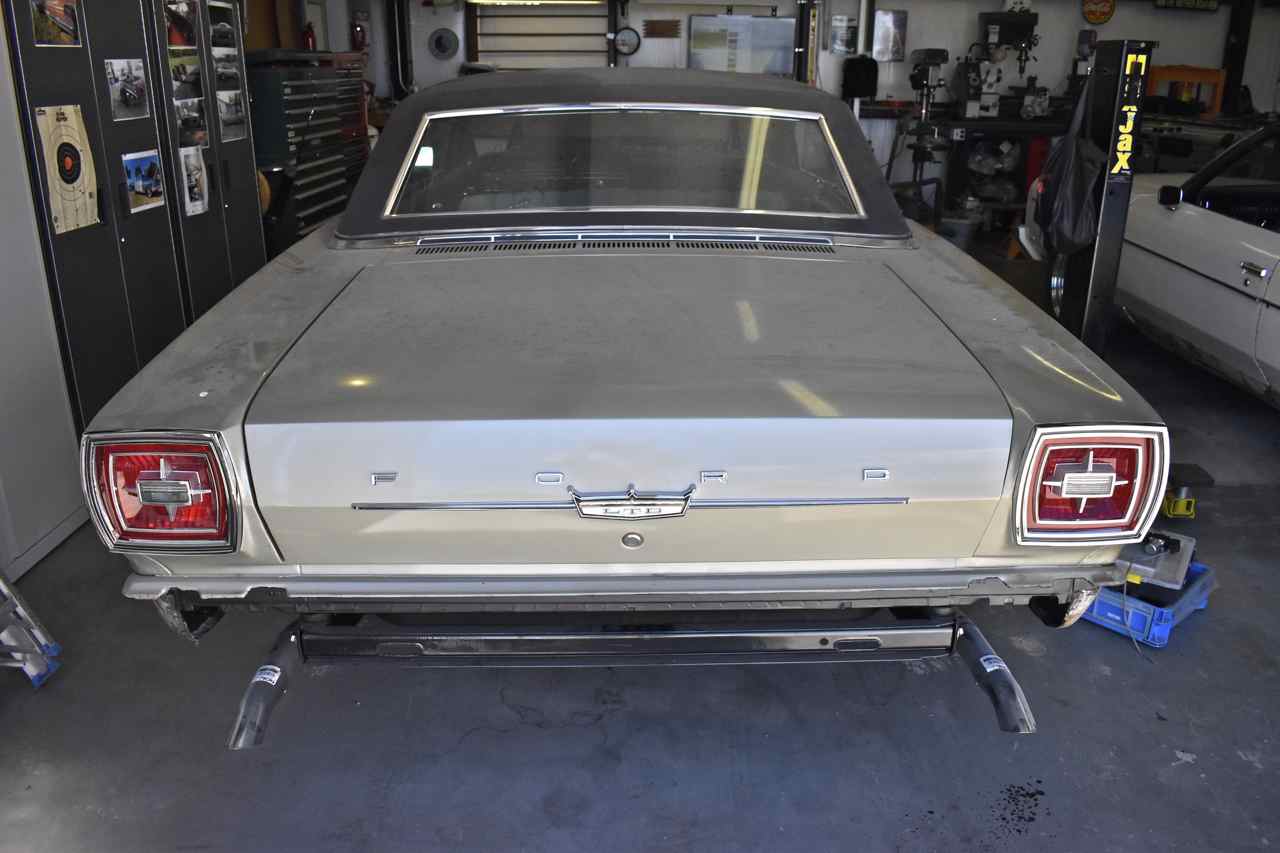
Next up I finally fitted some new shiny bits to the car. I was incredibly lucky to find an NOS deck lid spear, NOS FORD deck lid lettering, NOS Glowbrite lenses and repopped tail lamp housings. Also including a repopped rear view mirror, ball windscreen mount and clamp, as well as new gaskets for the tail lamps and a used clock that I made to work from two clocks.

At least everything in the rear fit ok. I'll leave all this installed till it's time to respray the car. Those new letters and spear look amazing.
I also started on the electrical rewiring. What a project this will be for sure.
I bought an assortment of GXL wire in assorted gauges and colours, as well as SXL and TXL wire. I'll use GXL for engine bay area and body routing since it's the thickest insulation. I also bought assortment of connectors, boots and a used Panther fuse box for the engine bay.

Since the Ford fuse box terminals new are ruinously expensive I ransacked two Panther fuse boxes from the salvage yard and will use the existing pigtails to splice into underside of the fuse box where they cannot be seen.

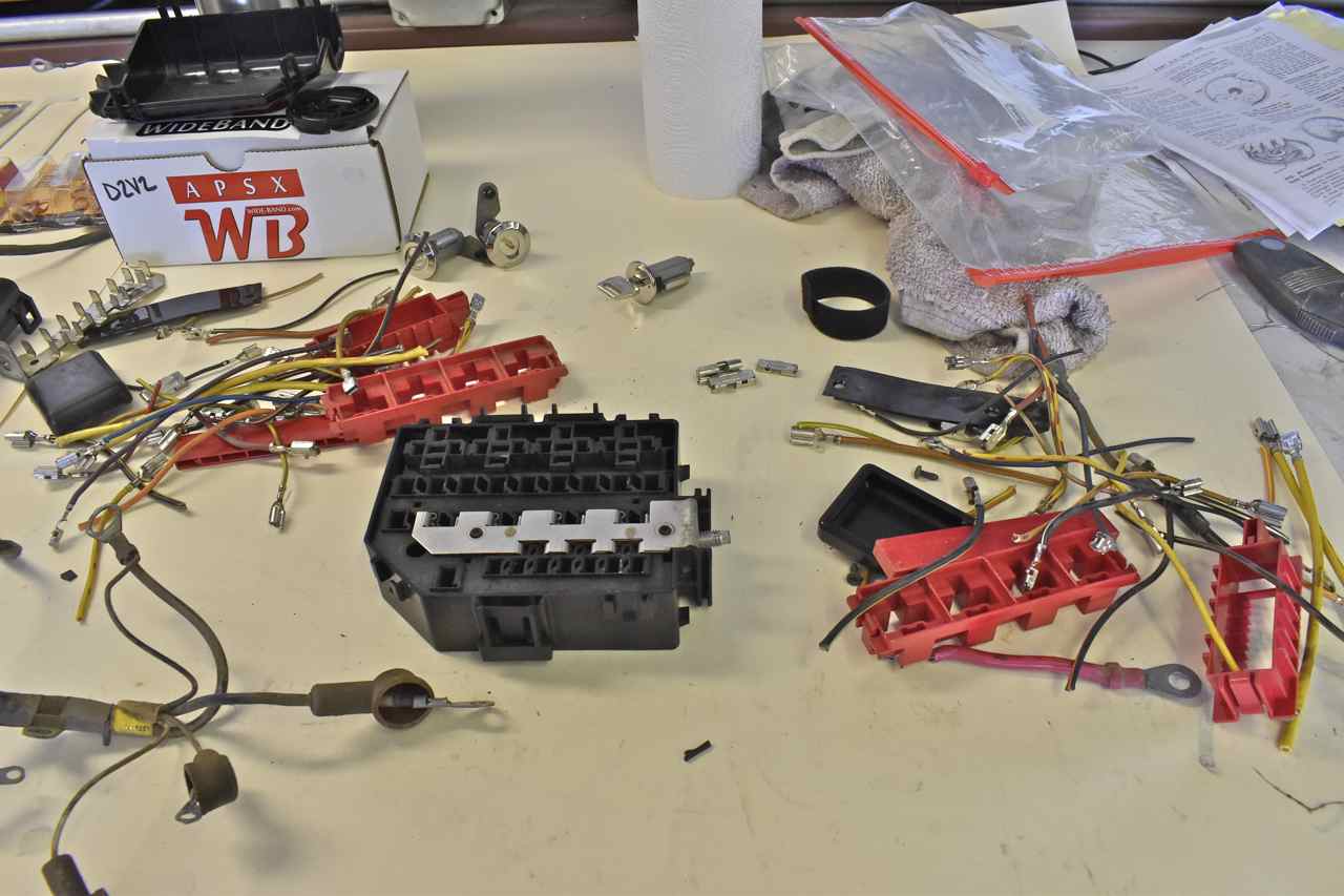
First up was replacing the charging system harness and making a modification or two.

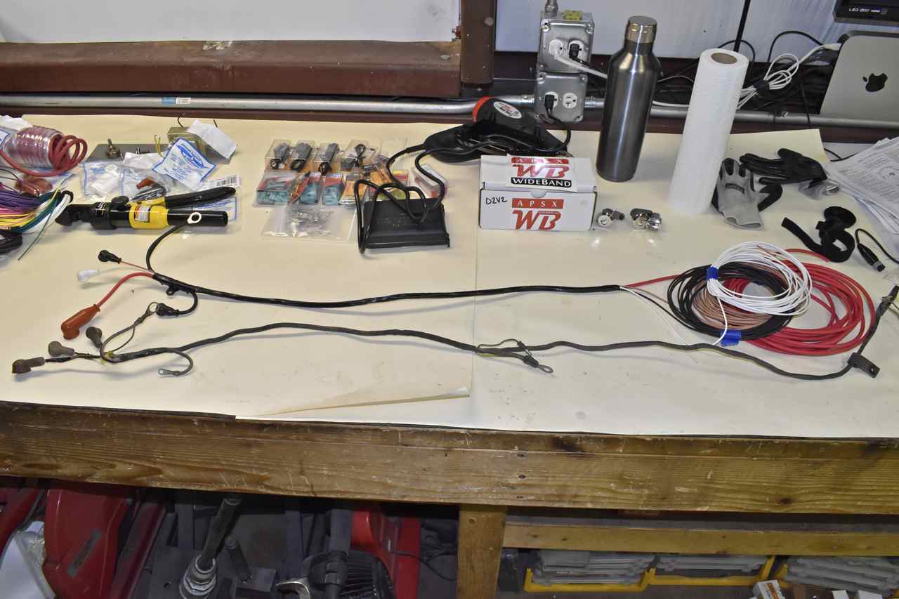
The original harness has one fusible link to the charging system. The fusible link is probably 50-60 amps (takes the output of the alternator) which is fine as that lead is 10 gauge wire. Problem is they fused the voltage regulator/field feed from that same high current fuse and it uses 16 gauge wiring. If the field starts to short or the voltage regulator for that matter there is a chance that 16 gauge will turn into a toaster element before the heavy fusible link melts. It could in theory start a fire.
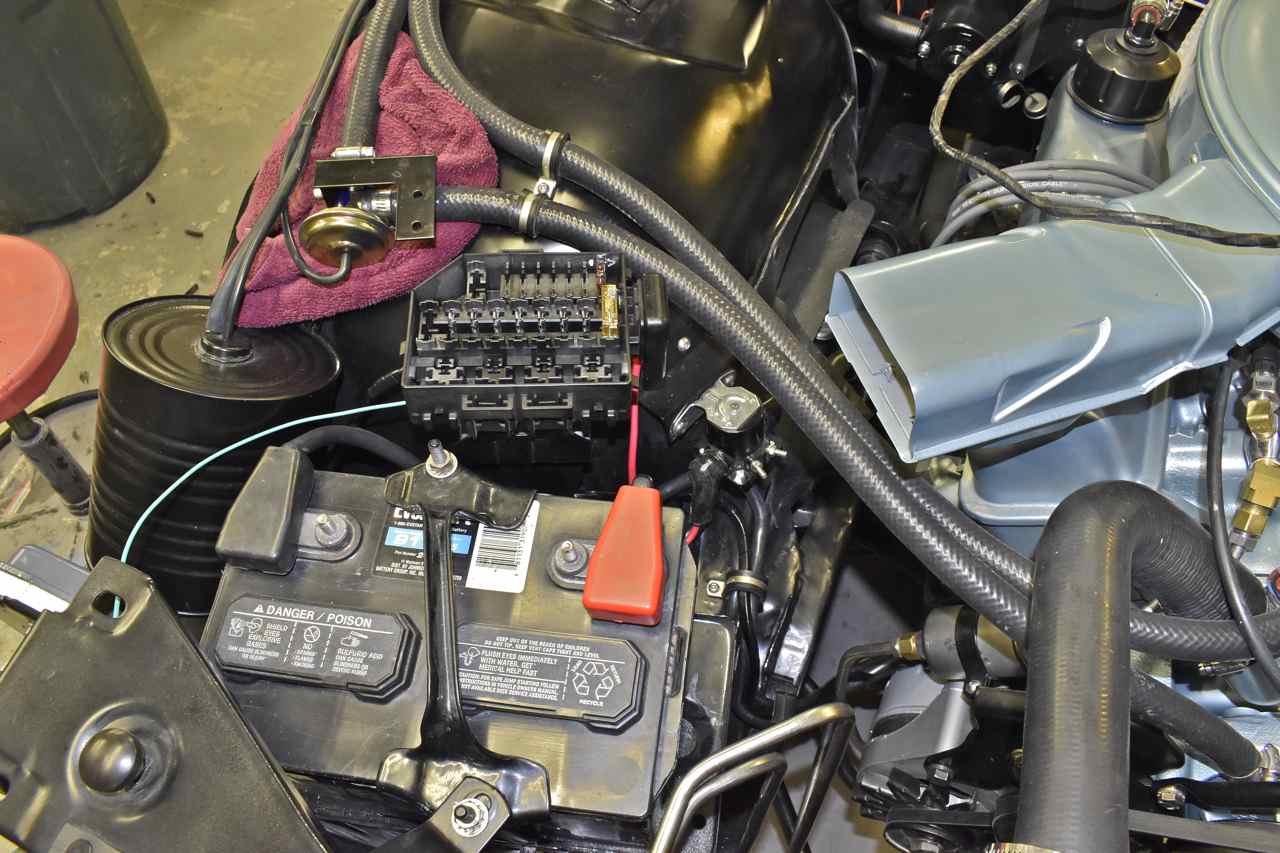
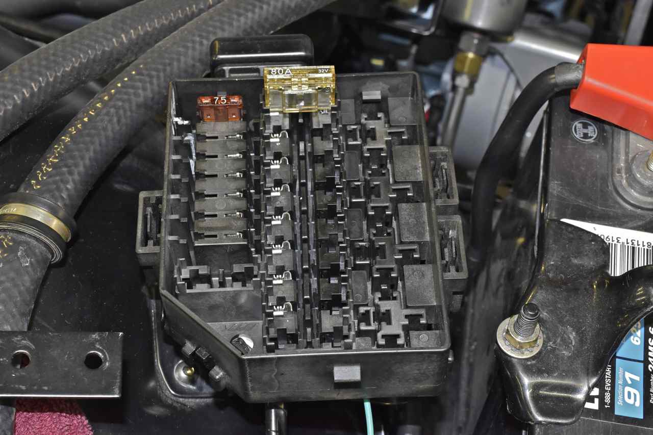
I decided to break up the charging system into two sections and fuse them separately. One is the alternator output and the other is the field/voltage regulator feed. Since the alternator is around 60 amps I decided to use an 80 amp MAX fuse in the Panther fuse box to fuse it instead of a fusible link. For the field portion I used a smaller 7.5 amp ATO fuse.
Slowly the Panther fuse box gets populated. I intend to use every relay spot (4) and just about every MAX and ATO fuse slot available.

Most of the plastic connectors like the voltage regulator connector were so old and brittle I bought new connectors, but they come with pigtails on them. However the crimp terminals for these are a dime a dozen so I bought those and crimped in my new wires directly to the new connector.
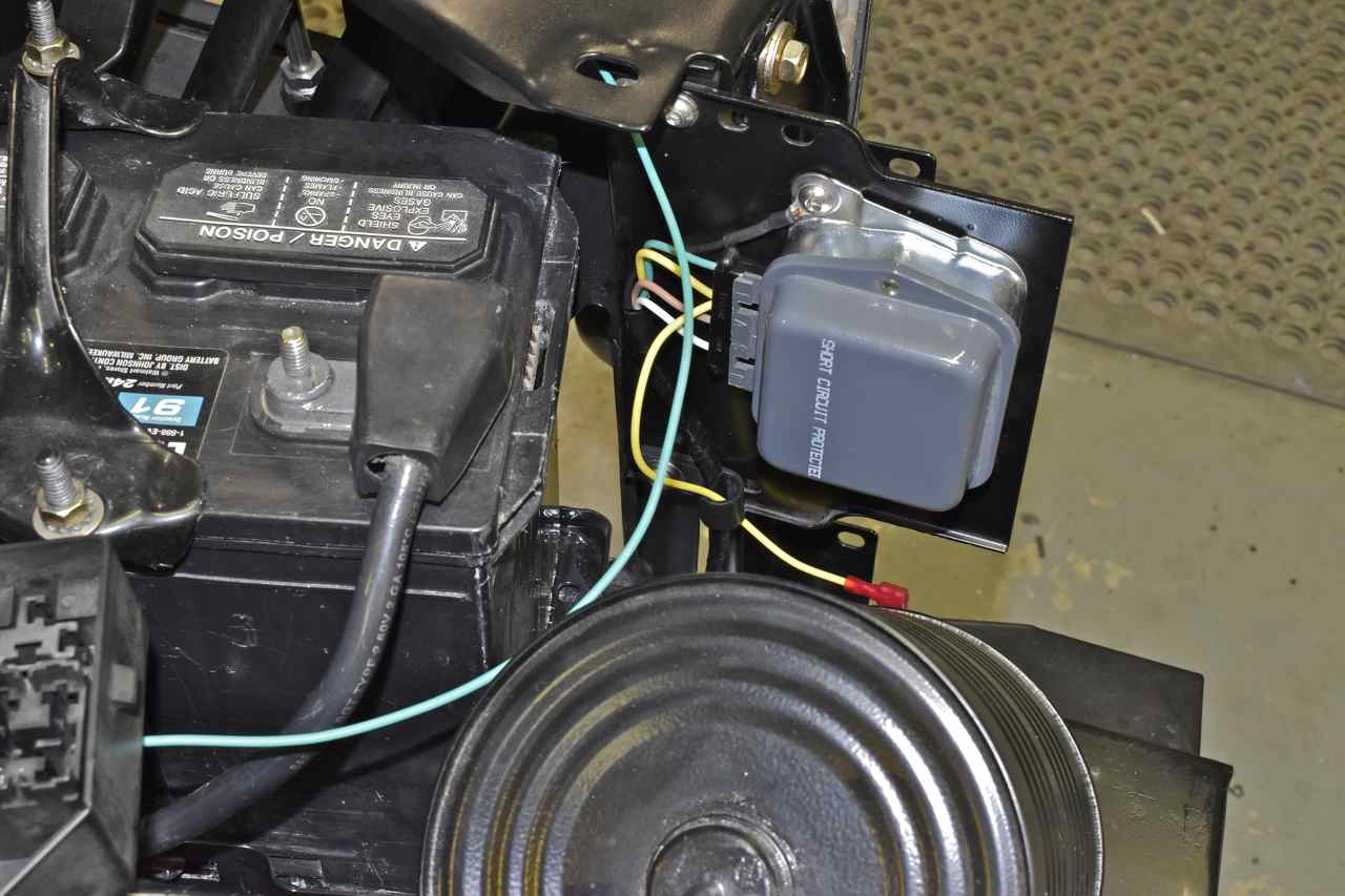
A better view of the fuse box. Tested the new charging system (I rebuilt the alternator, new electronic voltage regulator and now harness) and it works brilliantly. At hot idle the battery voltage is 14.5 volts, at hot idle with the air con blasting it's around 13.6 volts.
I'll have more to post on the wiring as well as the body. I'm working here and there on different sections at a time.
Hope you enjoyed.
Cheers
Click here to continue to part 38