1966 Ford LTD Resto-Mod : 034 Midland Ross Brake Booster Rebuild - part 1
2023, November 14
1 - 2 - 3 - 4 - 5 - 6 - 7 - 8 - 9 - 10 - 11 - 12 - 13 - 14 - 15 - 16 - 17 - 18 - 19 - 20 - 21 - 22 - 23 - 24 - 25 - 26 - 27 - 28 - 29 - 30 - 31 - 32 - 33 - 34 - 35 - 36 - 37 - 38 - 39 - 40 - 41 - 42 - 43 - 44 - 45 - 46 - 47 - 48 - 49 - 50 - 51 - 52 - 53 - 54 - 55 - 56 - 57 - 58 - 59 - 60 - 61 - 62 - 63 - 64 - 65Hello,
It's been ages so I thought I'd tack back on to this thread. I've come up across a couple of problems to overcome. First was the brakes in that there's little power assist and secondly the engine, the pistons were made incorrectly and I missed it.
The new pistons (round two) are on order and being made, should be here this week with a bit of luck. In the interim I am tackling the brake problem. So this car originally came with power drum brakes. My only major modification I did to the brake system was to replace the single jamb jar (reservoir) master with a dual reservoir master and install a shuttle valve with warning switch.
Come to find out the Midland Ross booster, of which this car was outfitted with, can be finicky when disassembled reusing the original seals, especially the big funky seal. So when I took it apart to powder coat it I didn't get the seal with years of seat imprinted precisely in the same place and boost was very low.
I ordered a kit to rebuild this booster which contains all the seals and key parts. The pictures below are the process. I have to say the Midland Ross booster is much easier to overhaul than the Bendix style booster.
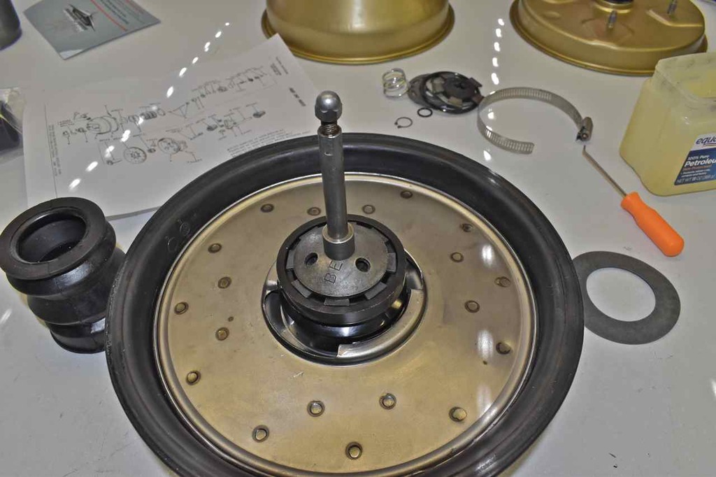
My Midland Ross 9" booster and the seal kit from Harmon Classic Brake Parts.

I did have to make this little tool (if you can call it that) to remove the input rod. I quickly made this partially from a pipe that I use to install control arm bushings sitting in the press parts pile and the rest was a bolt with washers welded to it.
So all you do is tighten the nut and it draws out input rod easily, don't try to yank on it, it needs steady increasing pressure to come out. Plus the internals are bakelite plastics, sudden shocks can easily crack this.
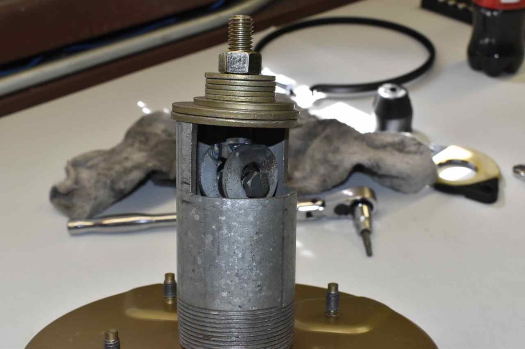
So once the input rod is removed, the band is removed and unfurl the seal lip around the front half and it just comes right off.

The rear half just slides off too.
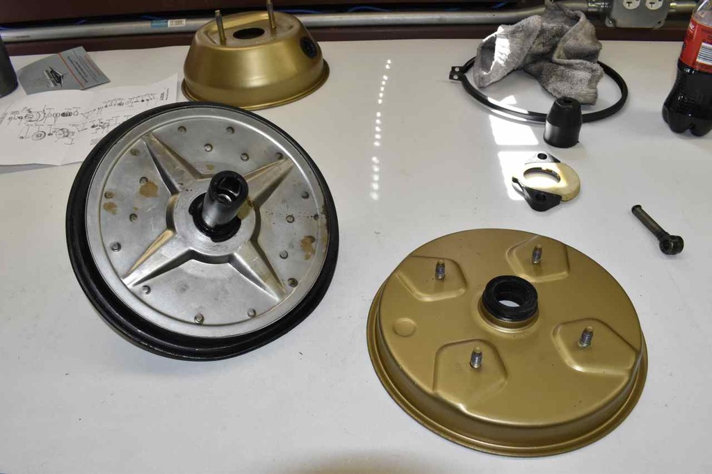
Remove the master push rod
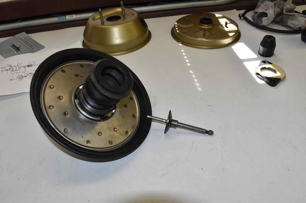
The control valve rotates into the diaphragm assembly, I used aluminum jaw protectors and lightly (do not distort) the steel structure.
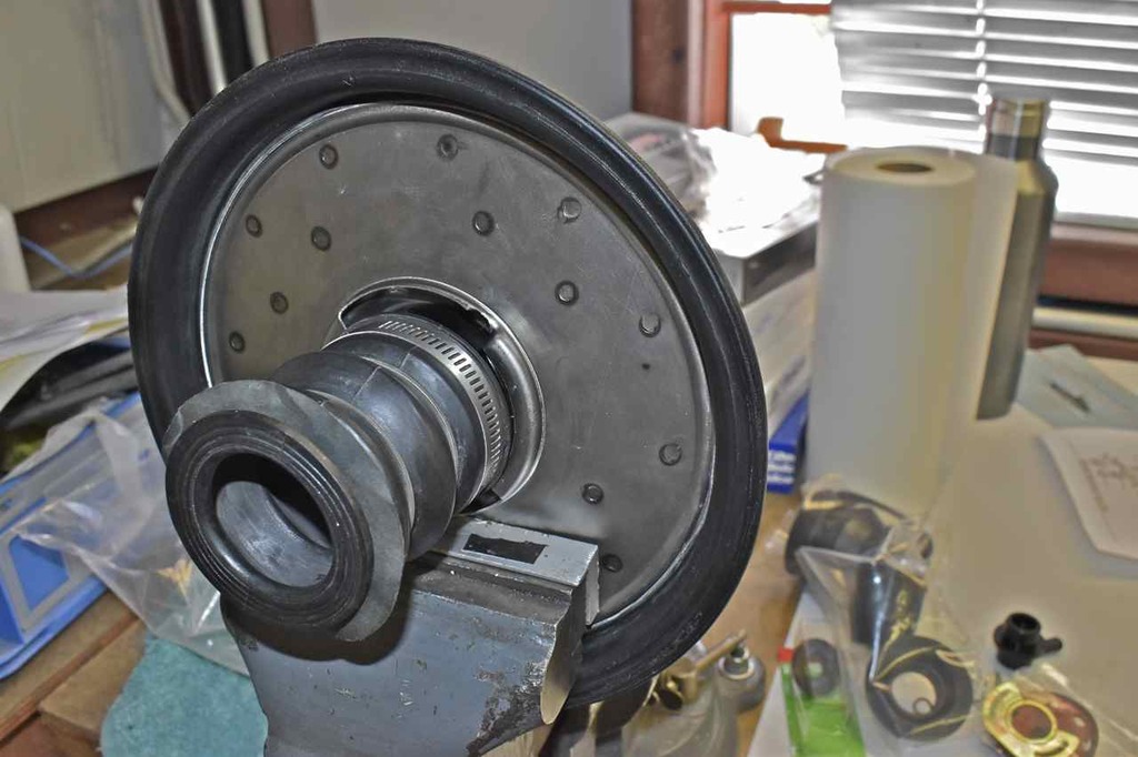
Give it a twist with gloves, use lube if yours is dry or rusty and slowly work it out. Remember this bakelite is fragile.
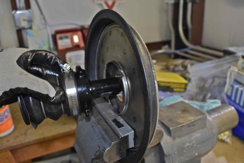
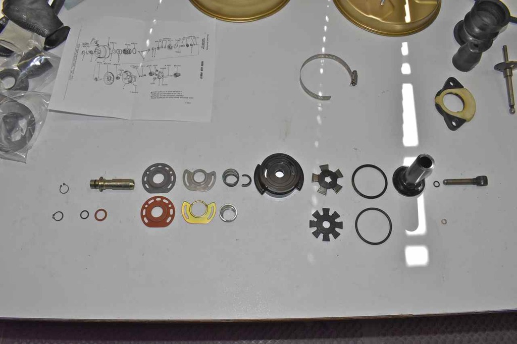
So far this is the line up of parts, there's really not much to a booster.

Remove this outside ring to release the innards of the control valve. It is slightly spring loaded.
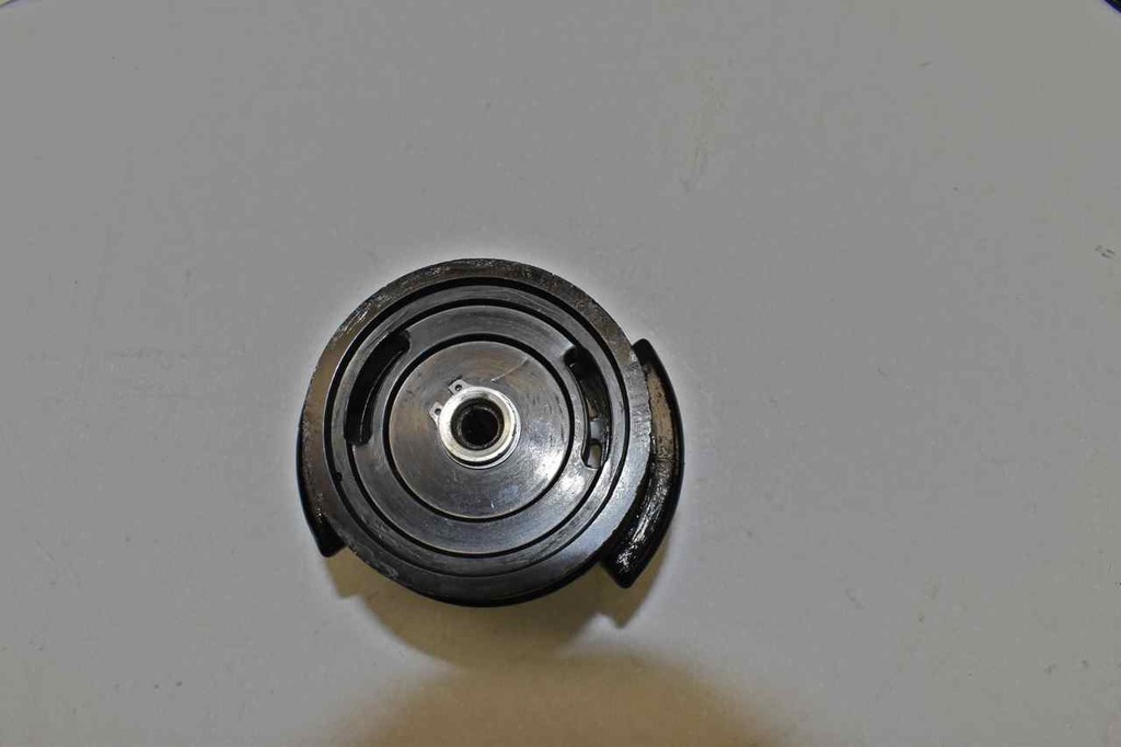
Innards
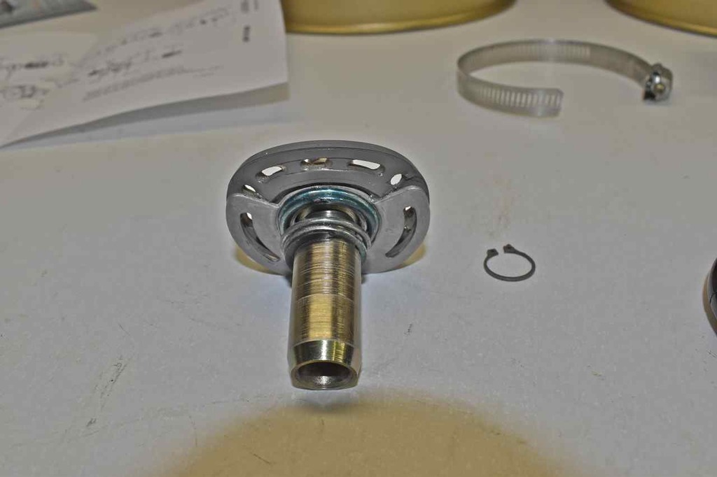
Line up of control valve parts.
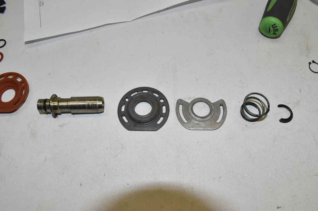
The top row are the original parts and the lower row underneath are the replacement parts. The crucial part is the orange seal (original is gray), this is the part that over the years has taken shape of the seat ports and has compressed.
New parts back on the stem portion of the control valve. Now I reused the old spring, I didn't care for the quality of the new spring.

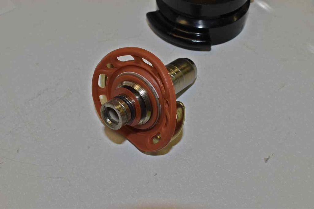
The orange seal has two holes (partially obscured) by the seal plate that must line up with protrusions in the plastic to locate properly.
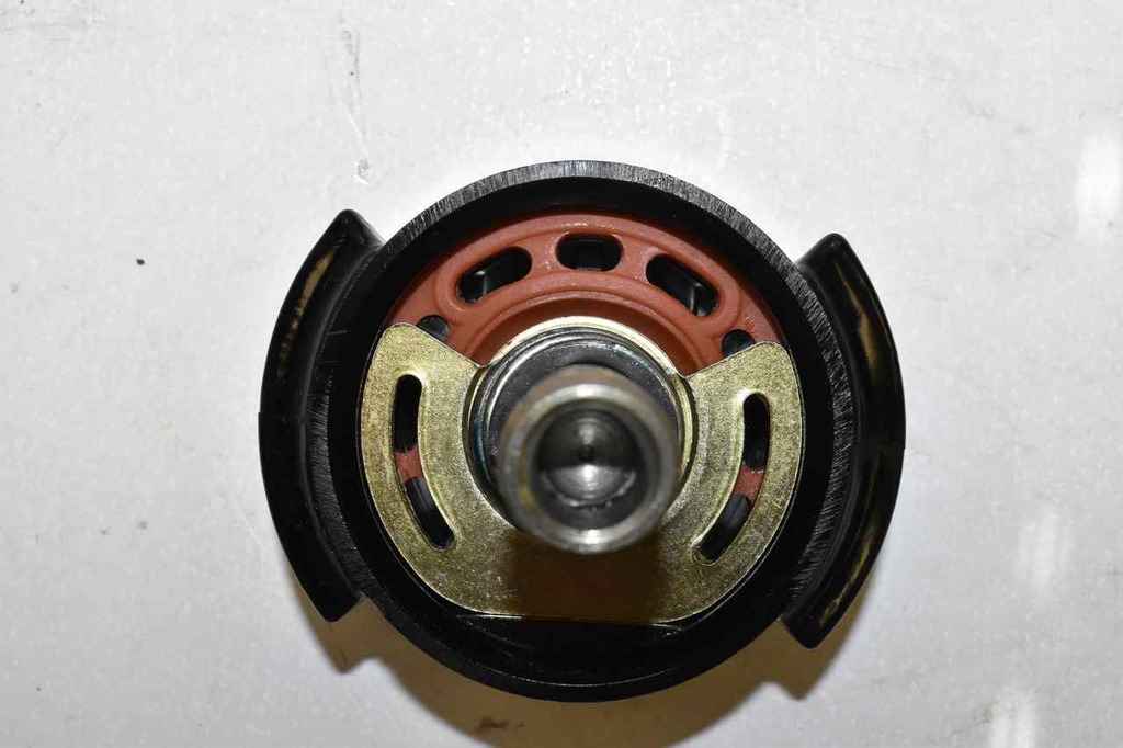
New external retainer ring
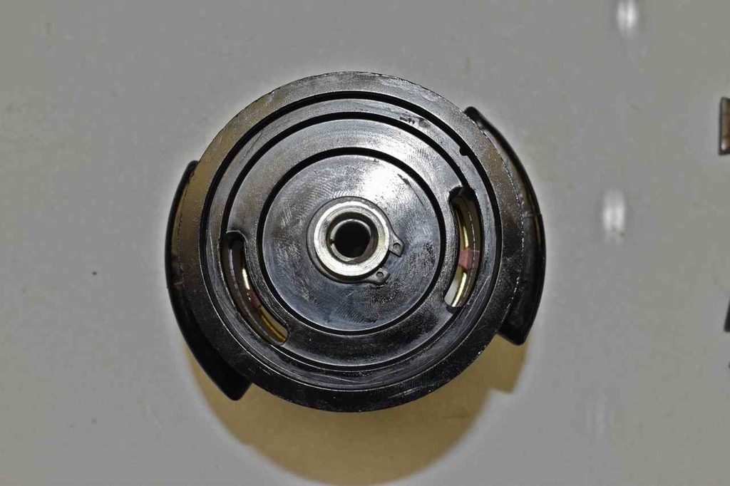
Put the tail stock back on with the new O-ring. Lube up the parts.
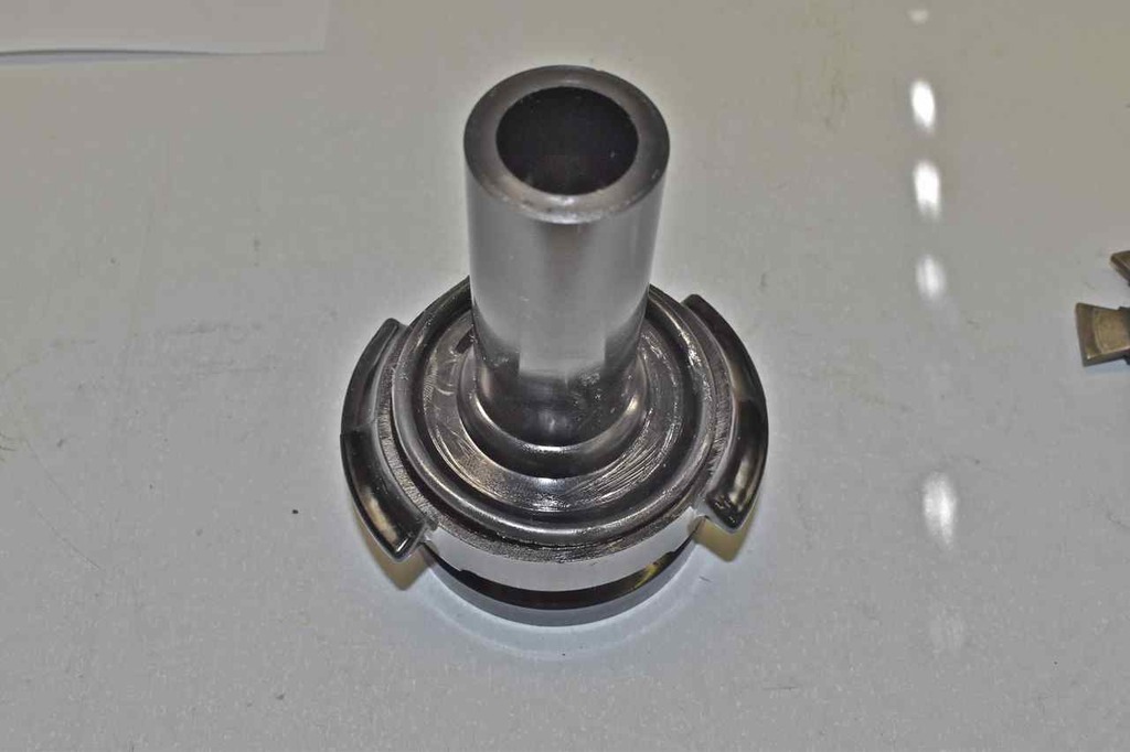
Reinstall in the steel diaphragm. Can use the rubber boot for more grip since with the new O-Ring it'll take some muscle to turn all the way to the stop.
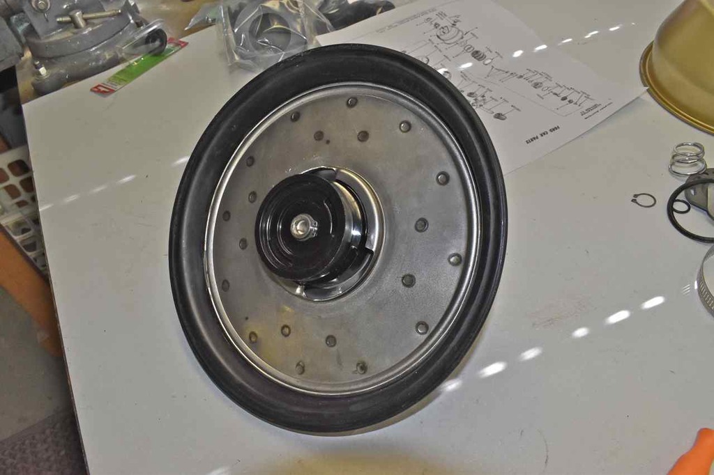
Reinstall the new reaction disc.
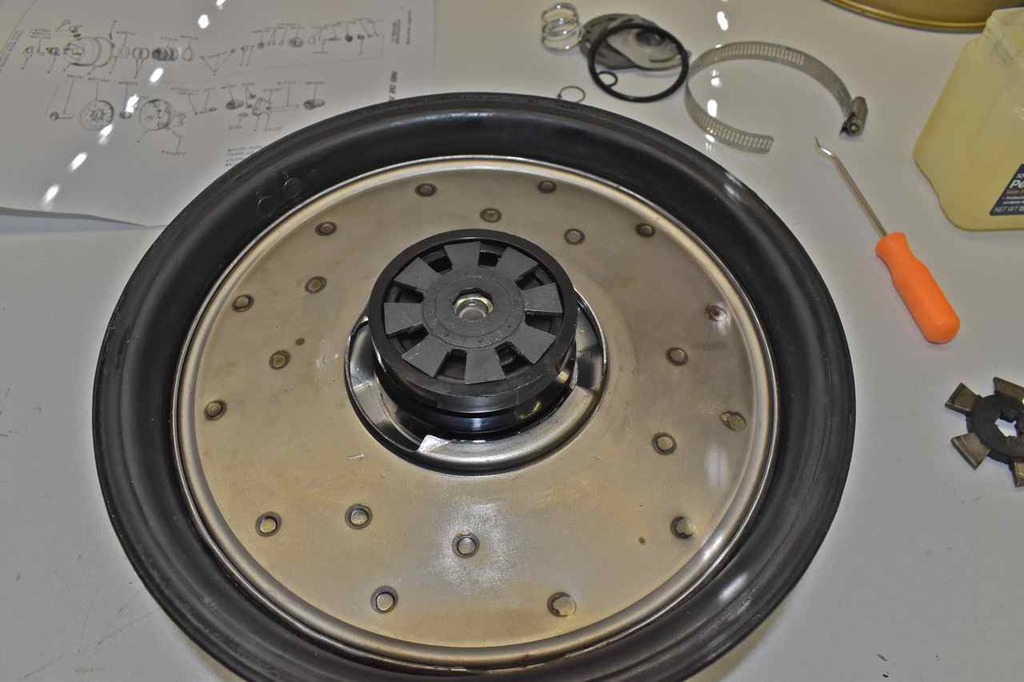
Reinstall the master push rod.
