1966 Ford Galaxie 500 XL Refurbishment : 010 Power Steering Gear Rebuild, part 1
2023, November 14
1 - 2 - 3 - 4 - 5 - 6 - 7 - 8 - 9 - 10 - 11 - 12 - 13 - 14 - 15 - 16 - 17 - 18 - 19 - 20 - 21 - 22 - 23 - 24 - 25 - 26 - 27 - 28 - 29 - 30 - 31 - 32 - 33 - 34 - 35 - 36 - 37 - 38 - 39 - 40 - 41 - 42 - 43 - 44 - 45 - 46 - 47 - 48 - 49 - 50 - 51 - 52 - 53 - 54 - 55 - 56 - 57 - 58 - 59 - 60 - 61 - 62 - 63 - 64 - 65 - 66 - 67 - 68 - 69 - 70 - 71 - 72 - 73 - 74 - 75 - 76 - 77 - 78 - 79 - 80 - 81 - 82 - 83 - 84 - 85 - 86 - 87 - 88 - 89 - 90 - 91 - 92 - 93 - 94 - 95 - 96 - 97 - 98Power Steering Gear
I have a couple spares of these '65-'68 power steering gears to choose from, but I decided to see if the gear out of the 1966 galaxie 500 XL was worth rebuilding. Well what a shock it wasn't too bad.
The one thing I've noticed on these Ford power steering gears is the bushing on the Pitman shaft wears. Now this was cheap on Fords part. The Saginaw power steering gear (also a possibility on these cars) and the Ford manual steering gear have a needle bearing for the Pitman shaft and doesn't wear.

If you can see the Pitman shaft move side to side with someone oscillating the steering wheel in the car whilst observing, then the bushing is worn and needs to be replaced. I have seen plenty of people just replace seals but never the worn bushing. The other item that wears in the Pitman arm as there is no grease fitting on them. This can be tedious hunting these down. This is an NOS Moog arm and an NOS Ford bushing. As of two years ago I knew Rare Parts was producing the Pitman Arm. The Pitman arm for the power and manual steering gears are different.
From what I've seen these parts are pretty well worn and sloppy at about 100K miles. Obviously the less city miles the less the steering is used and the less worn these parts will be. But these were pretty well and truly worn as I could move these wear parts side to side with just the strength of my hands/arms.
The Pitman arm from Rare Parts is a little over a 100 dollars as I bought one for the 1966 LTD as that was worn as well. To the best of my knowledge no one is currently making the bushings, once they are gone that may be it, kind of like the C4/C6 tranny mount for these cars. These bushings are about 10 bucks apiece and if you have a couple of these cars you intend to keep you may want to stock up.
Onward.
The murky brown mess. I am not going to show how to disassemble one of these as it's more cumbersome with the camera, rather I'll show how to put the clean pieces back together. You can just work backwards to take it apart.
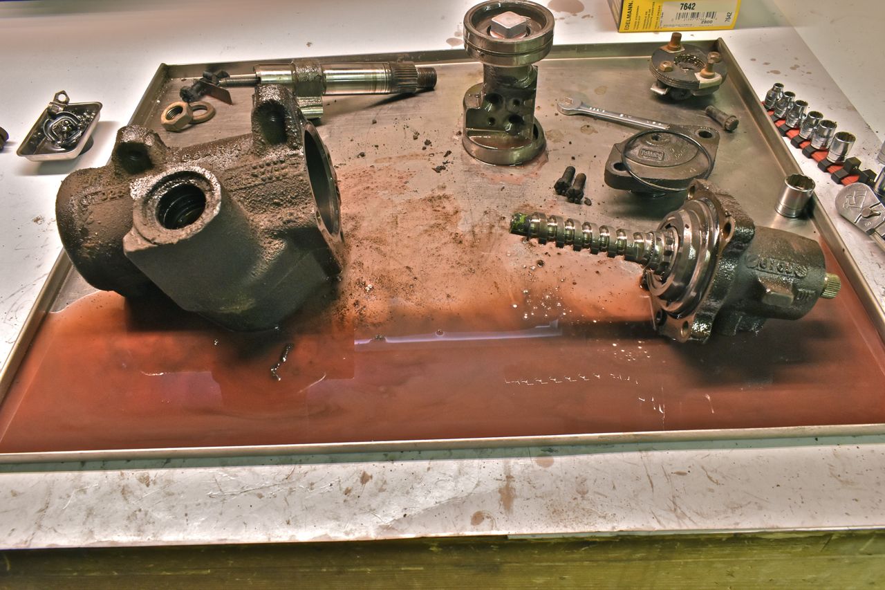
A wave of the Harry Potter wand (if only) and........
All the internals are cleaned, the case powder coated and most of the hardware blasted, blackened and clear coated.

Onto the nitty gritty details.
The cheap easy tool for removing the bushing is a 1/2 bolt with 1/2 grade 8 washers like above.

It's a close fit that works.
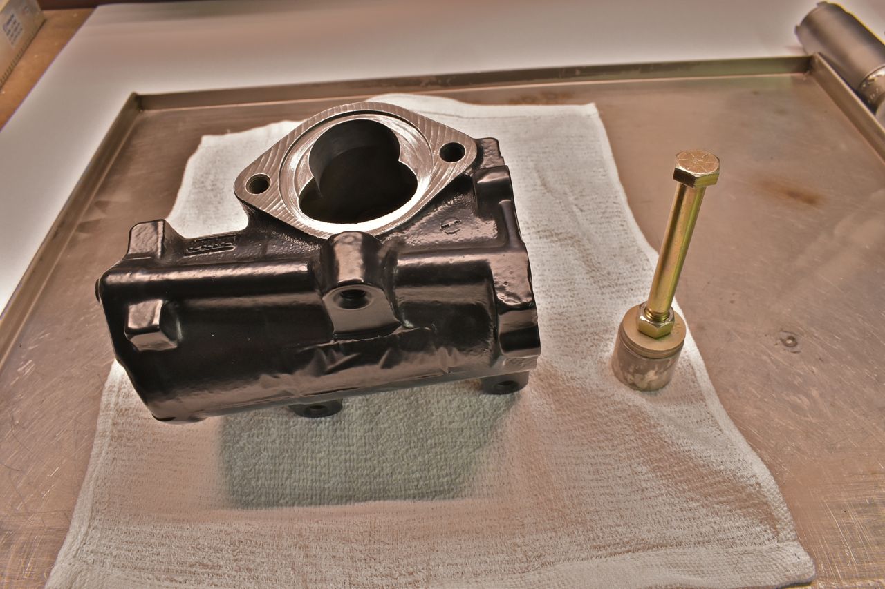
Now there is no stop lip on these cases, as a result you can press it in or out either end. I personally think it's easier to push downward as pictures to remove and install. Now a couple notes on detail. There are oiling groves in the bushing. You want to place the grooves as pictured because all the pressures and wear spots occur in two spots on the bushing only. The direction of side to side perpendicular to the long axis of the steering gear so you want to make sure lubricating oil can enter that area.
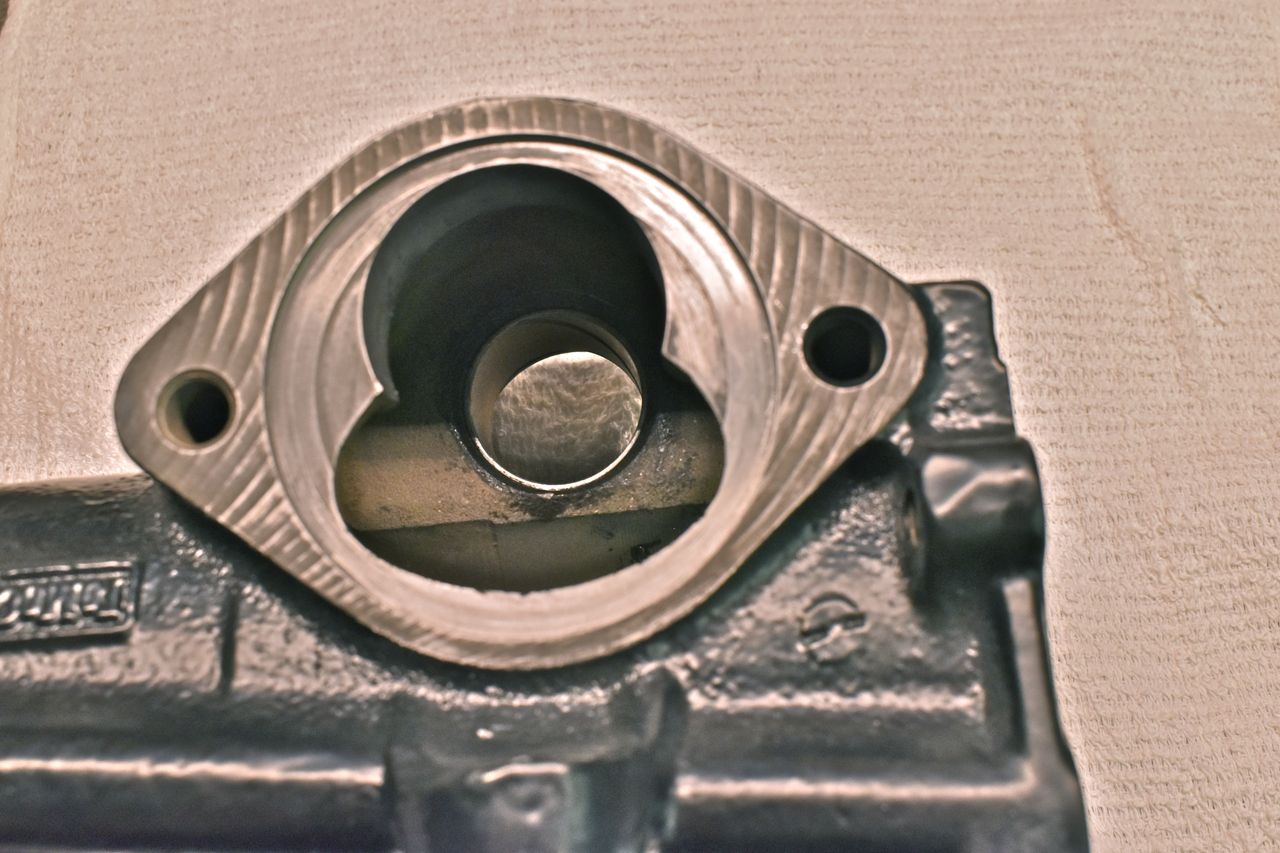
To install the new bushing you want to use a wider driver (left) to start and drive it flush with the case then switch over to the 1/2 inch bolt driver to set it down in the bore properly. This way you wont risk damaging the new bushing and also help start it true with the bore and not tilted.
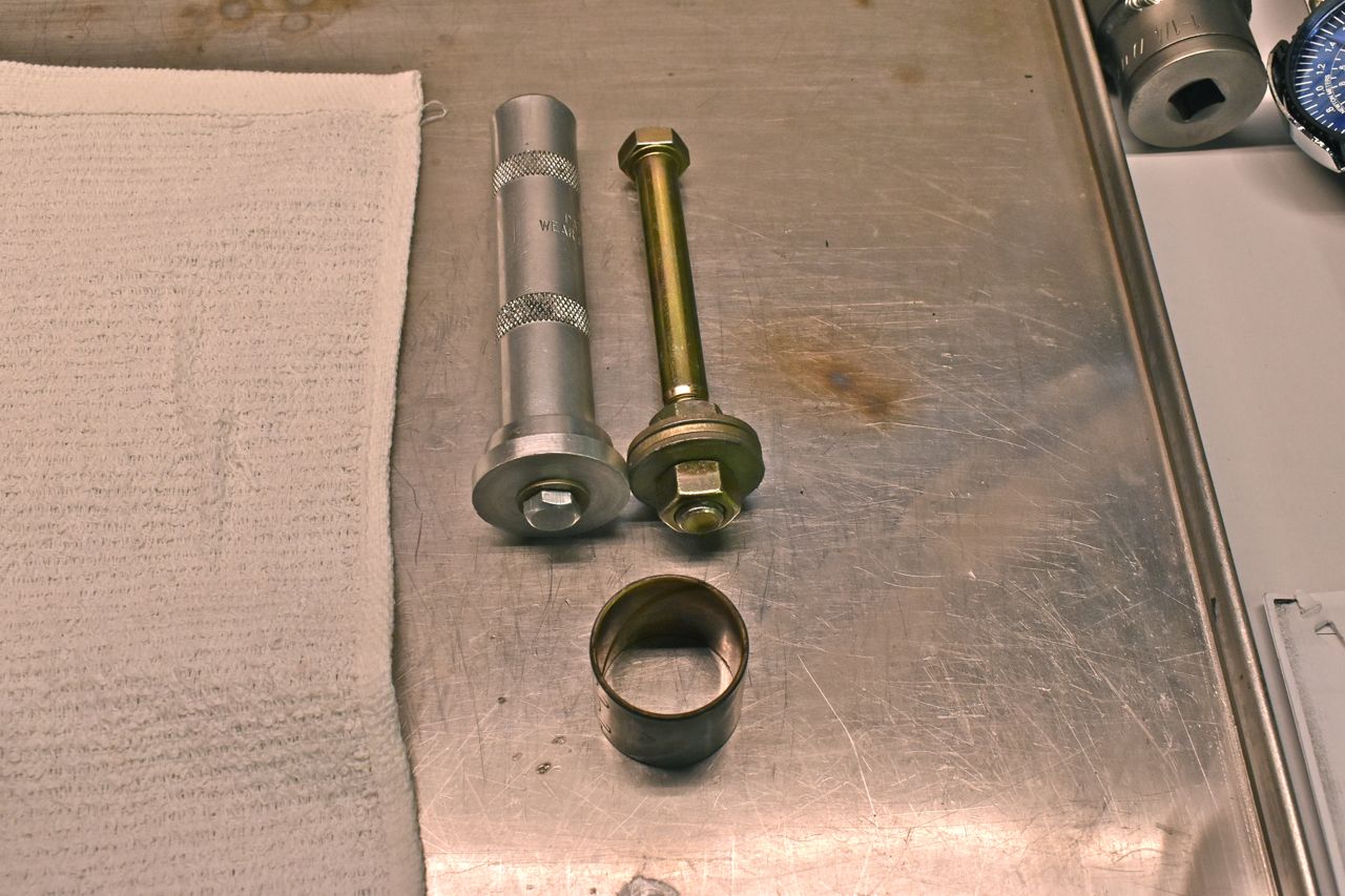
You can see the heavy wear marks only on one area. There are similar marks on the opposite side of the bushing as well. This is the only area it wears due to the intense side pressures of the Pitman arm articulation.

Next up the lower Pitman (Ford calls it Sector) shaft seals. Both rubber seals are identical. It just takes two due to the intense case pressures that can develop when hitting the stops on the control arms. (>1000 PSI).
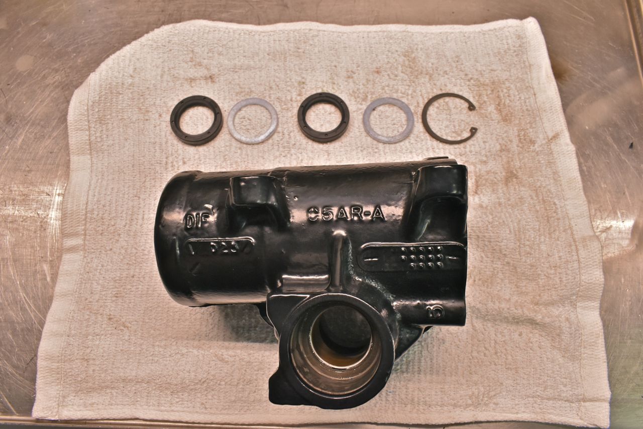
Use the largest driver that will safely fit without hitting the bore. I almost forgot to mention to use a liberal amount of Vaseline when assembling the innards. Now a word about these seals. There is no stop other than the bore lip for the bushing. However do not drive these all the way down. You want to drive these in just enough to get the snap ring on and no more. Now the pressures will seat the seals against the snap ring but if they have to travel any distance you risk damage or them not moving true and cocking off to the side and leaking.

It should look close to this.
Onto the control valve housing.

This is another potentially sticky wicket. For a bearing driver a 7/16" bolt with grade 8 1/2" washers works really well.

The 7/16" nut passes through the bearing middle, unlike the 1/2" bolt.
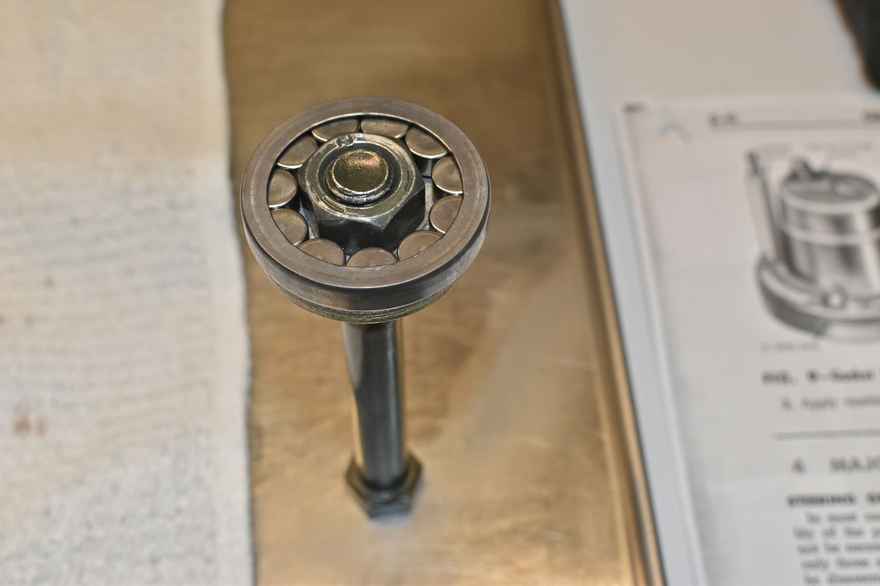
Now there is no bearing stop either on this. You have to just press it in far enough to either be flush or just proud of the seal ridge. If you go to far you'll start to block the fluid port at the top pictured.
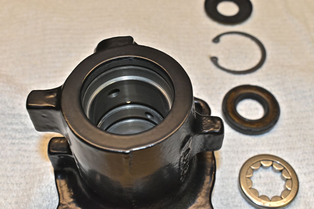
I highly recommend a shop press or an Arbor press as you have more control than with a hammer.

Like so.

Switch back to the normal seal driver to install the seals. Again only install the main seal far enough to install the snap ring. I was able to just use hand/arm pressure to push this in. Once the snap ring is installed install the dust seal.

Like so.
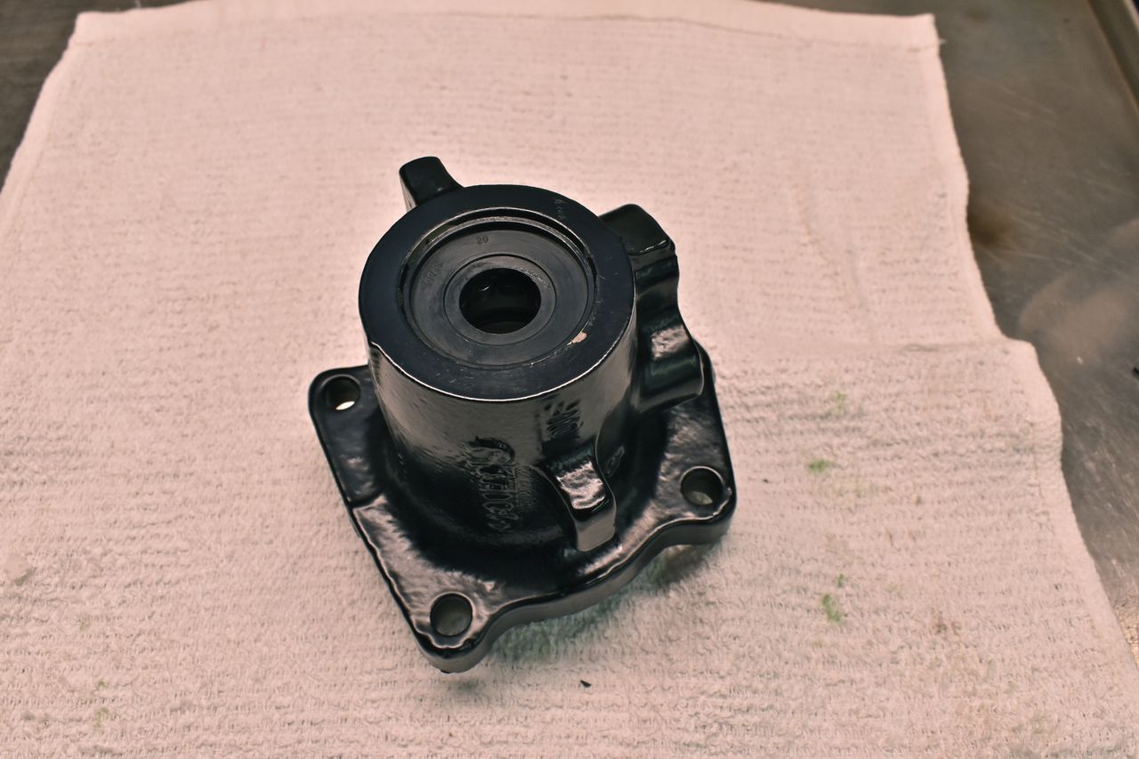
Now the tricky bit.
The spool valve needs to go on the same direction it was taken off as this will become more evident shortly. If you put the spool valve in backwards, you may find the power assist unequal from a left turn verses a right turn.

On this particular unit the V groove land was closer to the centre and this calibrated this way. I wouldn't trust this is the case with every one of these.

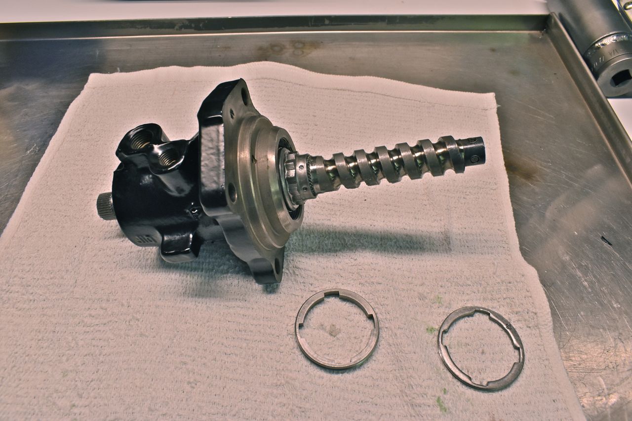
The thin washer on the left is actually a selective (calibration) washer that results in a neutral hydraulic balance with no steering input applied to the input shaft. This is needed because of the machining tolerances. This washer precisely locates that moveable spool valve in the bore in the housing at the top resulting in all the fluid going in and out the hoses with no flow diverted to the rack piston.

Lube up everything really good and install the spool/worm assembly shaft into the housing. It should seat and you should feel the drag from the new seals.
Here's how I fixture the control housing for the next step of torquing down the main and lock nut.
