1966 Ford Galaxie 500 XL Refurbishment : 021 Rear Disc Brakes, Axle Vent & Brake Lines
2023, November 14
1 - 2 - 3 - 4 - 5 - 6 - 7 - 8 - 9 - 10 - 11 - 12 - 13 - 14 - 15 - 16 - 17 - 18 - 19 - 20 - 21 - 22 - 23 - 24 - 25 - 26 - 27 - 28 - 29 - 30 - 31 - 32 - 33 - 34 - 35 - 36 - 37 - 38 - 39 - 40 - 41 - 42 - 43 - 44 - 45 - 46 - 47 - 48 - 49 - 50 - 51 - 52 - 53 - 54 - 55 - 56 - 57 - 58 - 59 - 60 - 61 - 62 - 63 - 64 - 65 - 66 - 67 - 68 - 69 - 70 - 71 - 72 - 73 - 74 - 75 - 76 - 77 - 78 - 79 - 80 - 81 - 82 - 83 - 84 - 85 - 86 - 87 - 88 - 89 - 90 - 91 - 92 - 93 - 94 - 95 - 96 - 97 - 98Rear Disc Brakes Continued and Axle Vent
Next up is to make the stainless right and left brake lines. I use to 10 gauge solid house wire to model them.

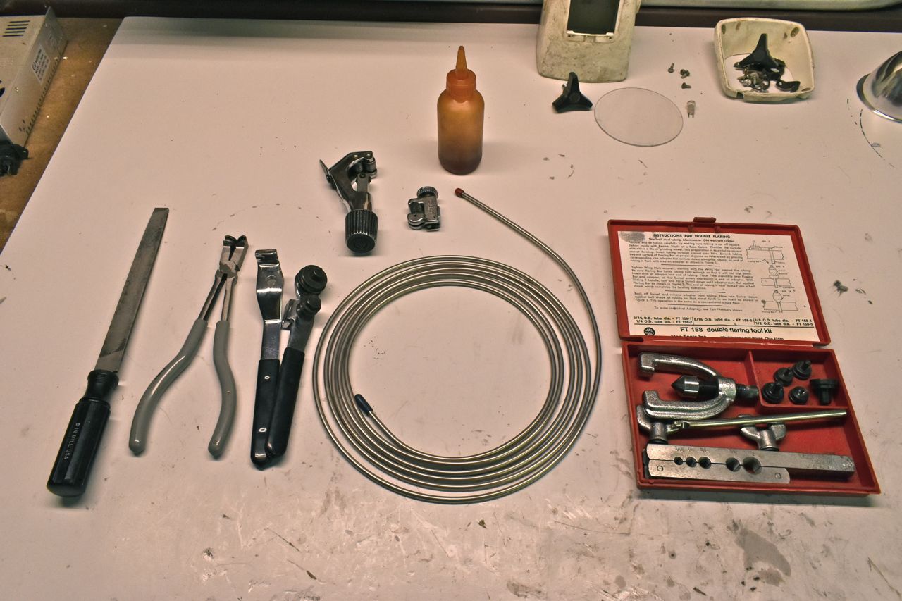
Armed with the bits to make them.
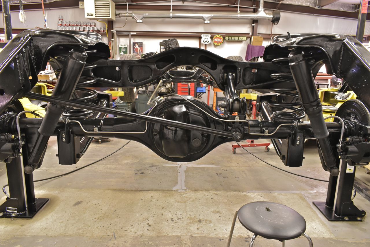
Done. Looks simple but good greif does it take time.
Vent hose.
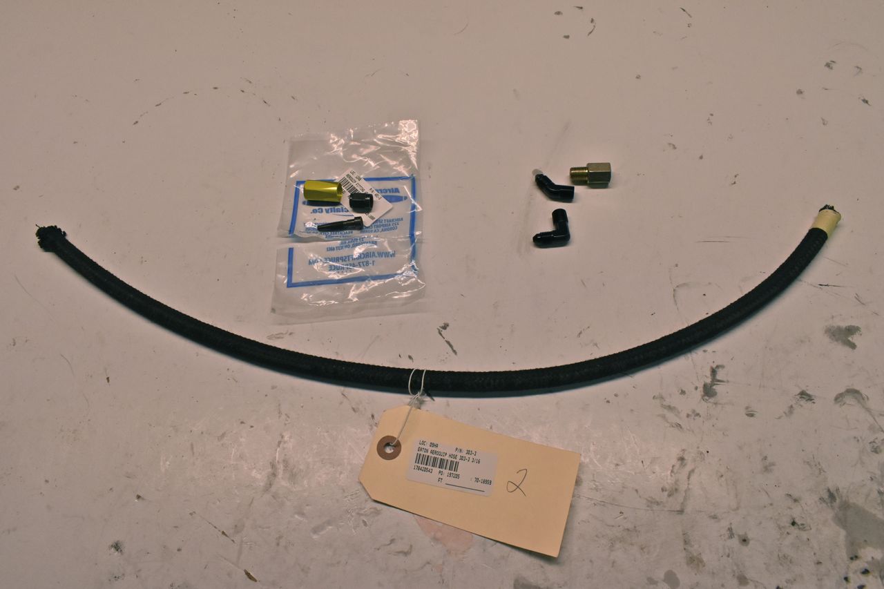
I wanted to show this in case anyone was interested in making the equivalent of a certified aviation line. If the Russel brake lines I whinged on about in a previous post fail, then this is exactly what I'll be using. These fittings and hoses are rated to 3000 PSI and you can make them at home.
Plus this hose and fitting is only a few bucks more than the automotive grade AN hardware speed shops sell like that Russel brake AN hose. So why not have the real deal.
First thing you need to do is true up the ends with a square cut.

These are the hose ends and installation tool. You need the installation tool for the size AN fitting you are using. In this AN-3.
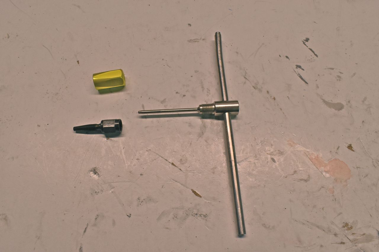
The outer sleeve actually threads onto the OD of the hose with a left hand thread. What you want to do is bottom it on the hose then back it off a couple of turns. This will help with starting the next step.
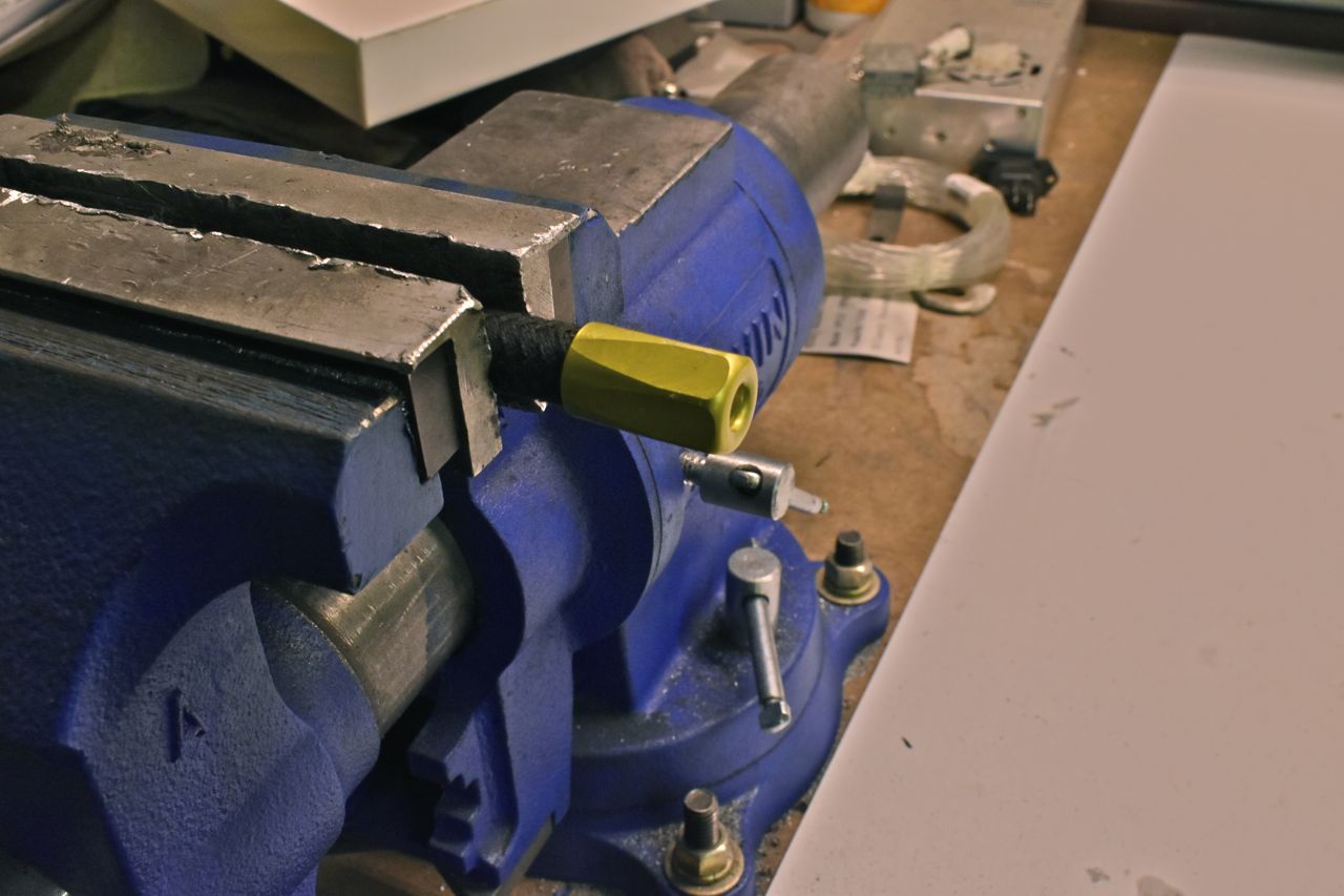
You have to tighten the fitting end on the tool first.

Then lube up the fitting and whilst pushing you turn to screw in as it has a right hand thread. Once the threads catch, finish tightening the outer cuff onto the hose fully then tighten the inner sleeve and remove the tool. Done. Easy Peasy.
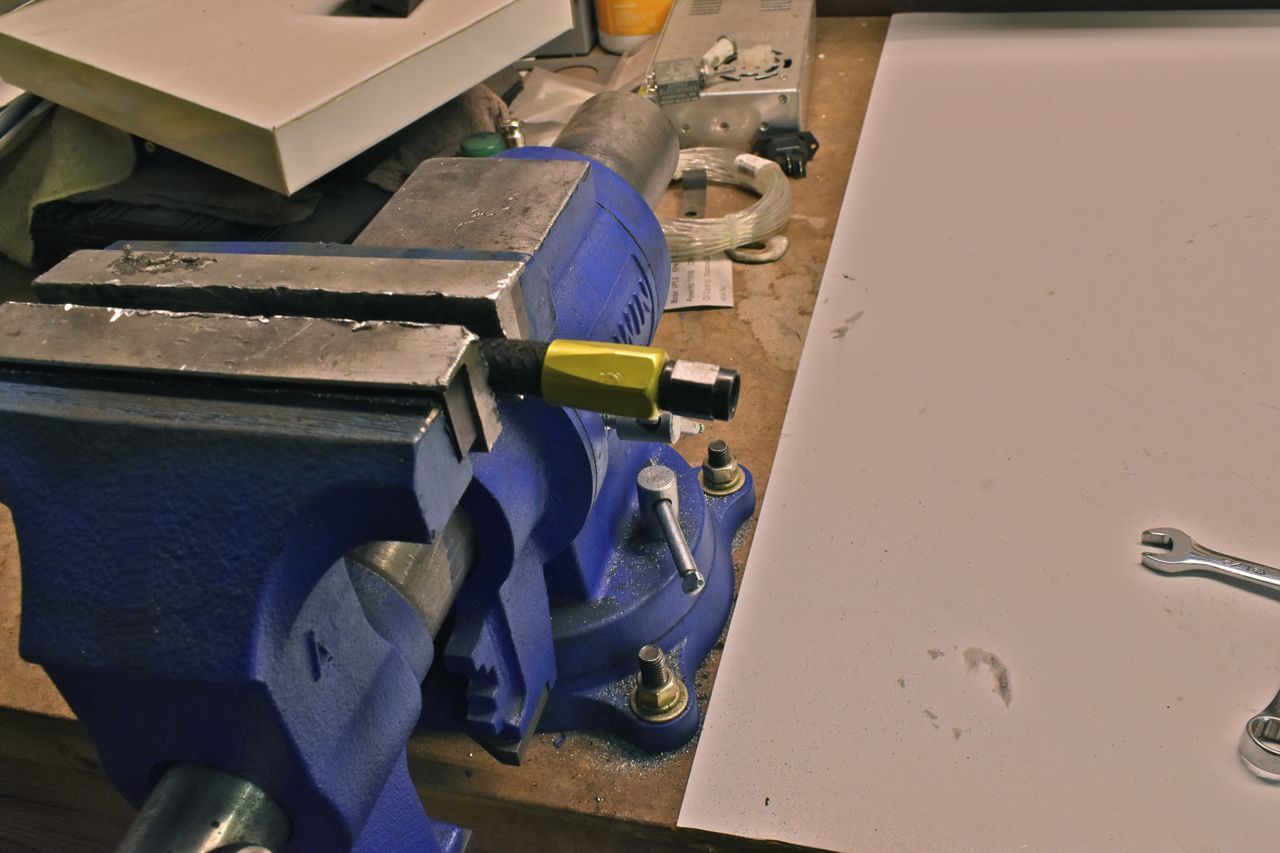
How this works is the outer sleeve cuts into the OD of the hose with a left hand thread. The inner sleeve not only cuts into the ID of the hose but also threads onto the outer sleeve. The right and left hand thread lock the fitting on and the inner and outer threads secure the fitting to the hose for high pressure use and is completely reusable. So when the hose ages, you unscrew the fittings and install on a new length of hose.
I couldn't find the fitting I used on the LTD with the pin hole, so I found this fitting online for turbos. Same thing really only this is steel and not brass.
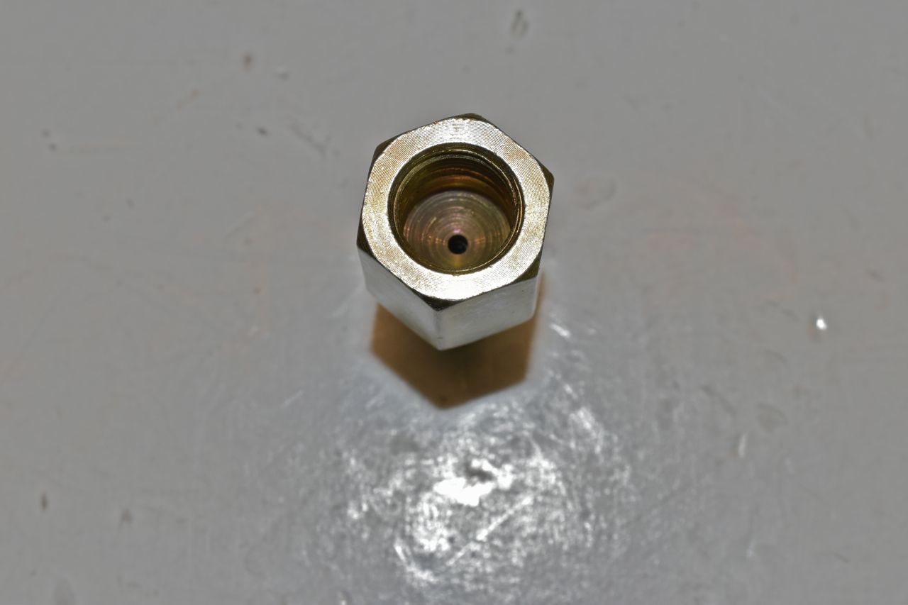
Here's the vent line done up. I didn't use the original hole in the top arch of the cross brace to stick the hose into as the factory did and here's the reason why. Out here we have very fine silty dust. The Ford 9" is an energy vampire, a very strong, yet energy vampire. As a result it generates heat and oil vapor from the vent hose if I stuck it in the brace I would have a build up of a mud ball in the frame and I don't want that. So it's arched on the back side instead where it's easy to clean on routine oil changes and full service.
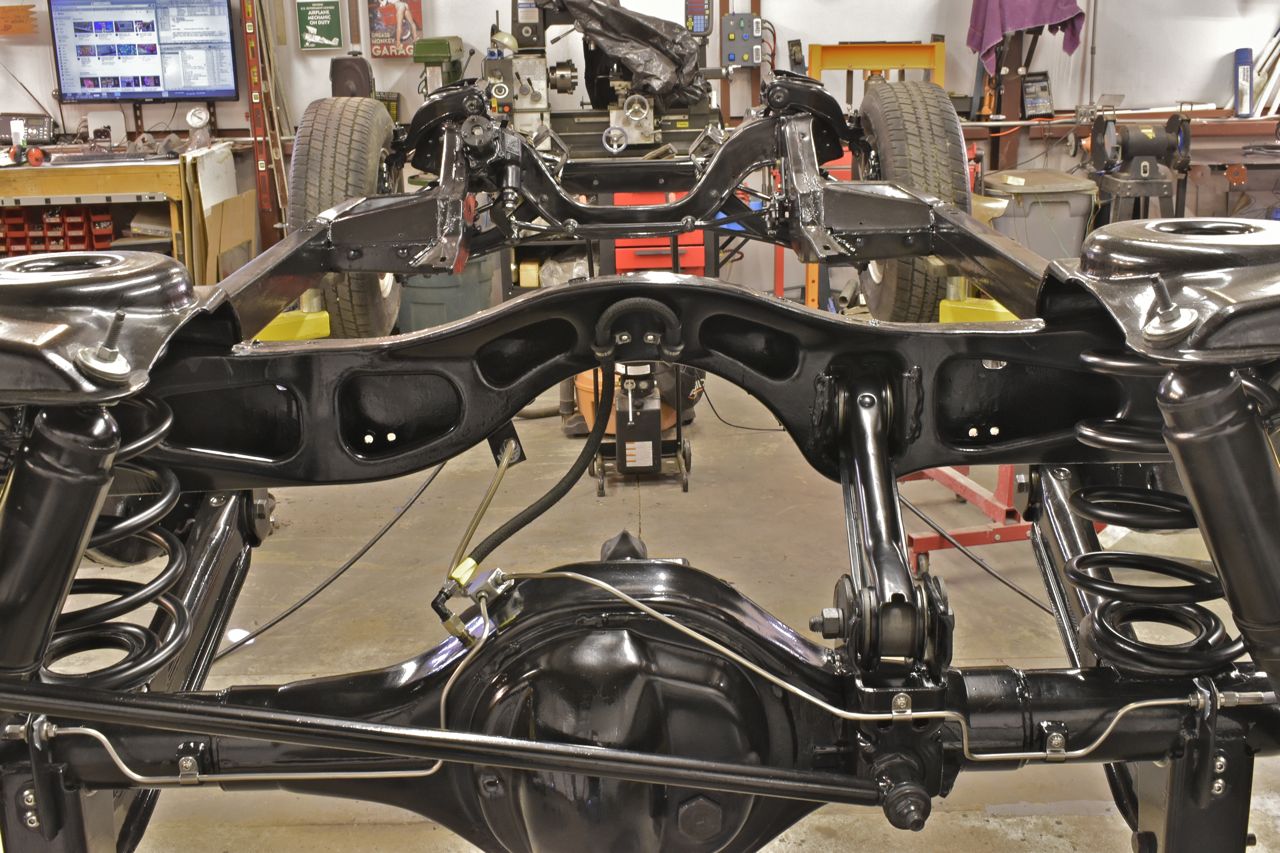
Back down on all fours.
Now onto the rest of the hydraulic brake lines and valving.

I'm using an aftermarket reproduction of the common GM combination valve. Now they sell these valves in Disc/Drum, Drum/Drum, or Disc/Disc. This is obviously the Disc/Disc.
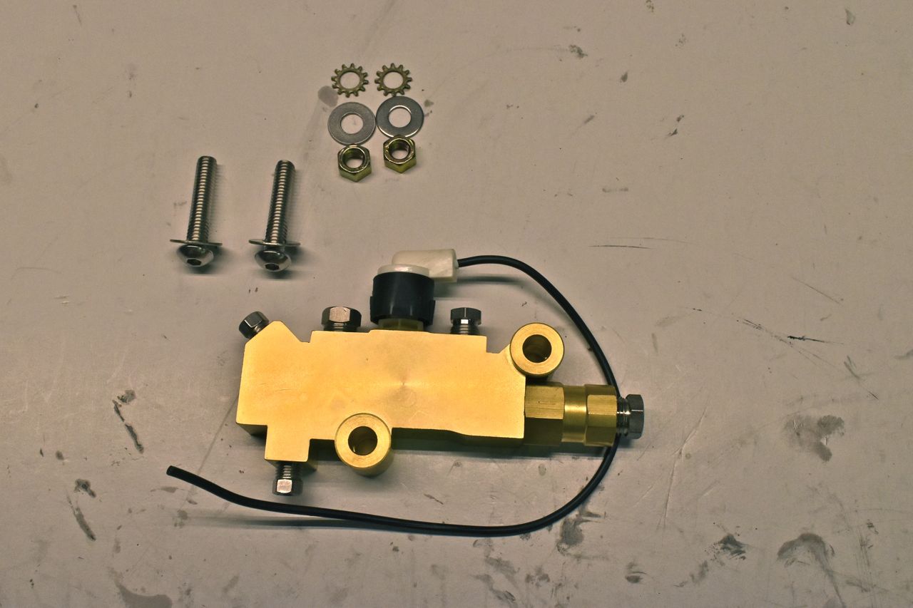
You're probably wondering what on earth is the difference. Here's what I've learned from all my research in a nutshell.
The Disc/Disc combo valve has two functions. There is the shuttle valve that moves to trigger the warning lamp if you loose front or rear brakes and then there is the limiting valve on the rear. Sometimes it's referred to a proportioning valve. In this case it's more of a limiting valve because of front and rear disc brakes.
Assuming you have a balanced disc brake system, meaning you have larger brakes up front (bigger pad area and bigger apply piston) than the rears and it's balanced to the weight, distribution, etc, then under normal braking you do not need anything thing else to affect pressures.
However in a panic stop, the front of the car will dip down, this is transferring weight of the car from the back to the front via the springs and inertia. This takes pressure off the back tyres and you can skid by locking the rear tyres up easier in a panic stop. So the limiting valve steps in an limits the rear pressures when they reach a high enough value so you don't lock up your rear brakes in a panic stop.
Do you need the limiting valve, no. Is it a nice feature, yes.
The reason why I'm using a GM valve is no one seems to be reproducing the Ford valves. I used a Ford shuttle valve on the '66 LTD only because it was on one of the parts galaxies as it was converted to a dual hydraulic system. I ran the Ford part number off it and it was from a '68 Mustang. I just rebuilt it and used it because I already had it.
This is substantially bigger and heavier than the '68 Ford Mustang shuttle valve so this will need a bracket made to hold this somewhere around here.

After spending some time debating where to exactly place this I came up with this bracket.

As you can see it uses the existing holes in the frame to mount. These two threaded inserts in the frame are normally used for the automatic column shift cars, but since this XL is a factory automatic floor shift they are free to use.
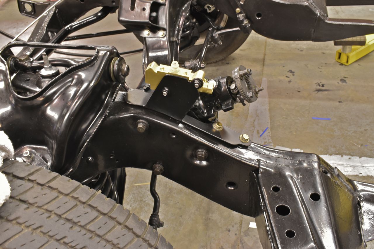
It also uses the original brake line distribution tee bolt hole in the side of the frame. The bracket holds the heavy GM combination valve quite stoutly in place.
Next up is plumbing the front two wheels to the valve.

The lines are pretty much routed as in the 1968 LTD/XL with factory disc brakes.


The lines and fittings are 304 stainless.
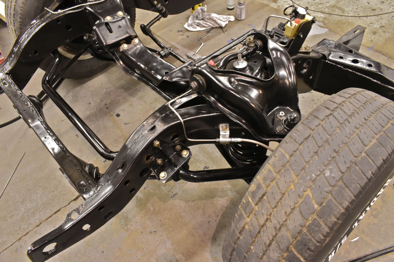
The rear line was next.
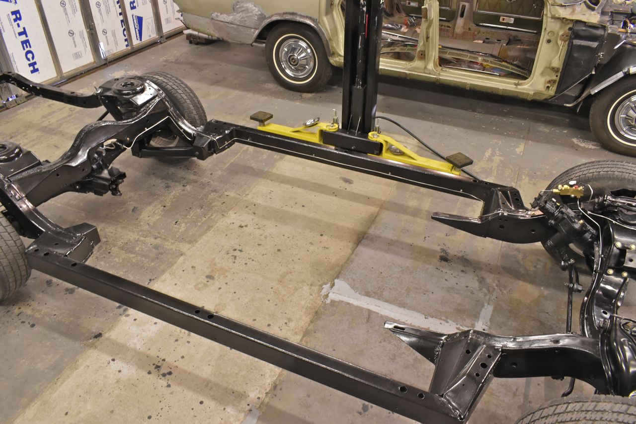
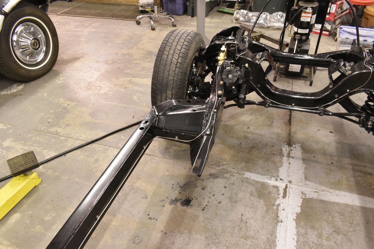
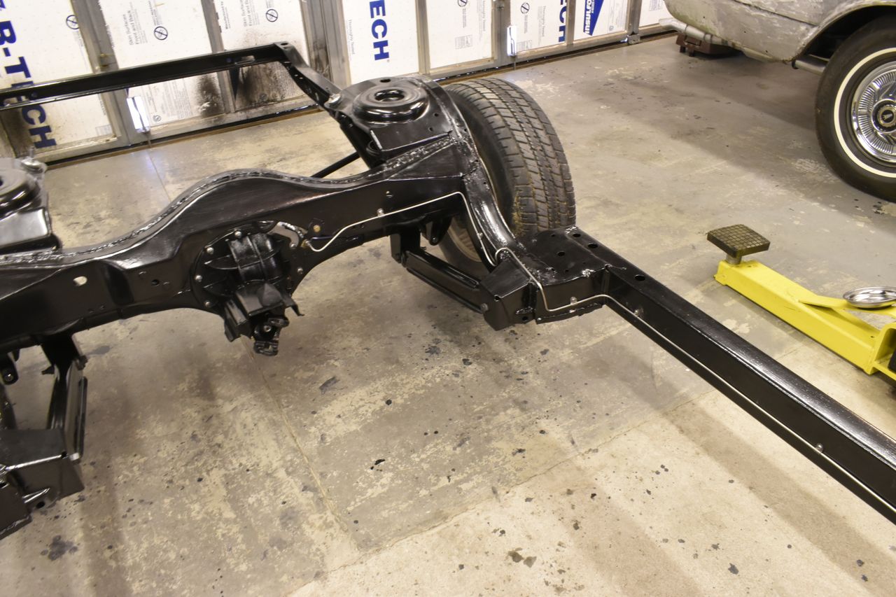
I'm taking a break from the chassis for a while as I'm a bit burnt out on it. I didn't even catch a basic mistake till well later on the rear brakes. Just goes to show when you're tired and hyper focused on the tiny details you can easily overlook the obvious errors.
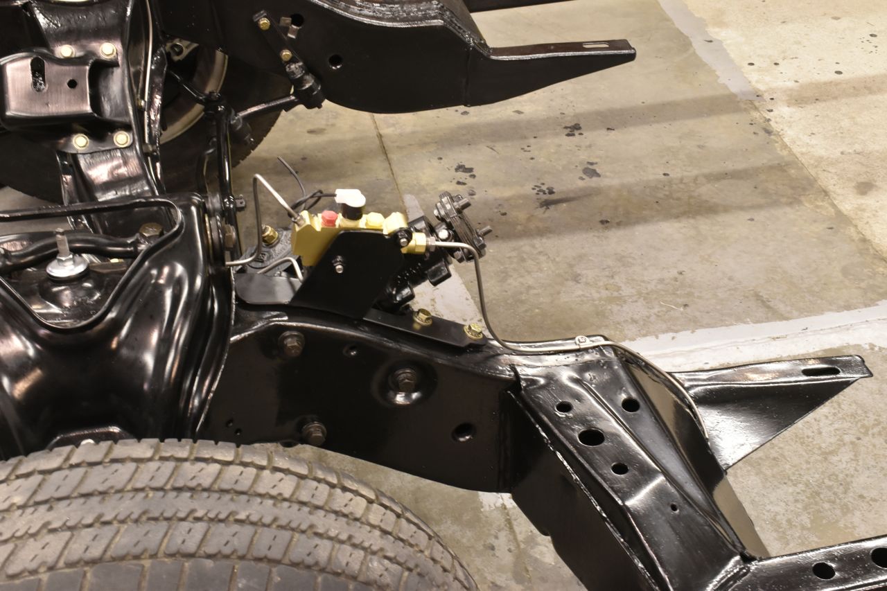
The error I'm referring to is the caliper on the right side. I was so focused on the left side when I sorted it out I just put together the right side. Well I used Panther calipers and these Panther calipers are the same for the right and left side. The Explorer backing plates are L & R (mirrored). What happens is the bleed screw on the left side is close to the top but is at the bottom on the right side.
Doh!
So I ordered Explorer L & R rear calipers and that should solve that.
Cheers
Click here to continue to part 22