1966 Ford Galaxie 500 XL Refurbishment : 043 Engine - Valve Train
2023, November 14
1 - 2 - 3 - 4 - 5 - 6 - 7 - 8 - 9 - 10 - 11 - 12 - 13 - 14 - 15 - 16 - 17 - 18 - 19 - 20 - 21 - 22 - 23 - 24 - 25 - 26 - 27 - 28 - 29 - 30 - 31 - 32 - 33 - 34 - 35 - 36 - 37 - 38 - 39 - 40 - 41 - 42 - 43 - 44 - 45 - 46 - 47 - 48 - 49 - 50 - 51 - 52 - 53 - 54 - 55 - 56 - 57 - 58 - 59 - 60 - 61 - 62 - 63 - 64 - 65 - 66 - 67 - 68 - 69 - 70 - 71 - 72 - 73 - 74 - 75 - 76 - 77 - 78 - 79 - 80 - 81 - 82 - 83 - 84 - 85 - 86 - 87 - 88 - 89 - 90 - 91 - 92 - 93 - 94 - 95 - 96 - 97 - 98A Little More Engine Progress
Time to assemble the valve train.
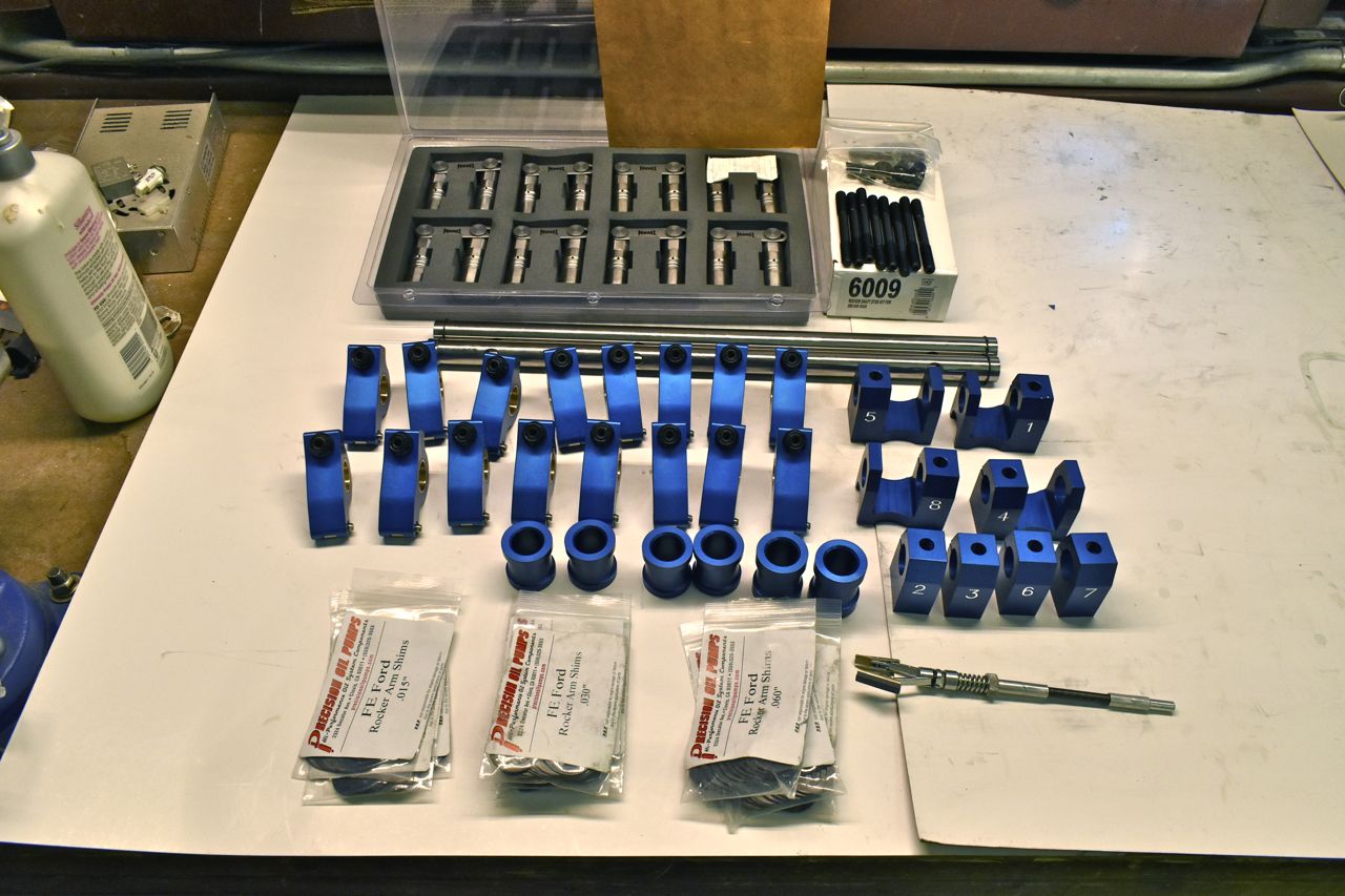
More engine jewelry. All these parts are Precision Oil Pumps. It's like an erector set of valve train parts. Those bags of shims are needed to space the rockers over the valves on the shaft. The stock FE just uses tension springs to keep the rockers positioned on the shaft because the valve springs on old OEM stock flat tappet cams were so weak they weren't worried about the rocker sliding over and the pushrod dislodging. Obviously with the high spring tension of the roller cam you want the rocker precisely positioned and secure from floating around on the shaft. The Rockers have replaceable bushings and are hone to fit, hence the little brake hone. The new rocker shafts are stronger than the old ones Ford used and I bought the supported ends because the stock Ford end rockers are unsupported. The shaft has been known to break off with stiffer valve springs. All these reasons are why the original valve train is in the rubbish bin and none of the old stuff is being using.
Ford has bolts that hold down the rocker shaft but I use the studs, so you use Locktite and screw them in to keep them from spinning.
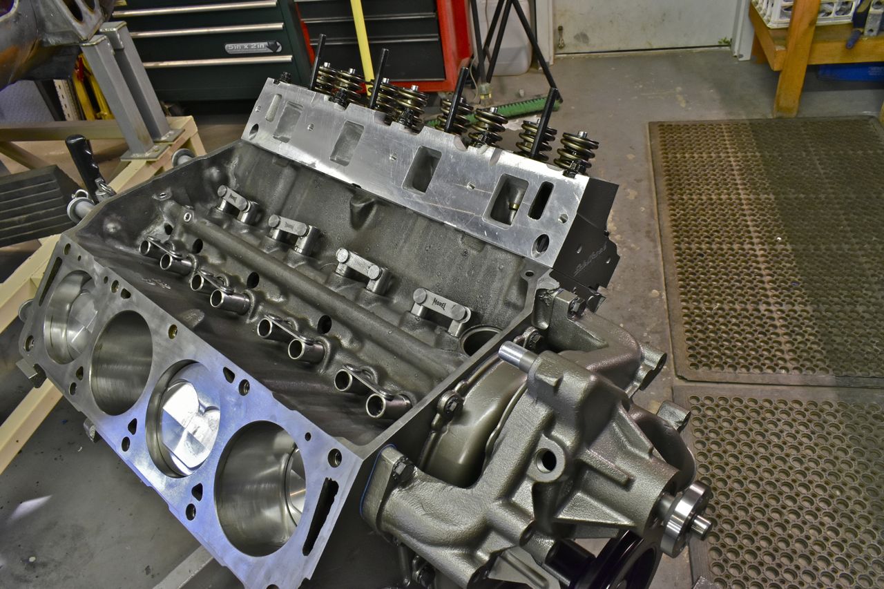

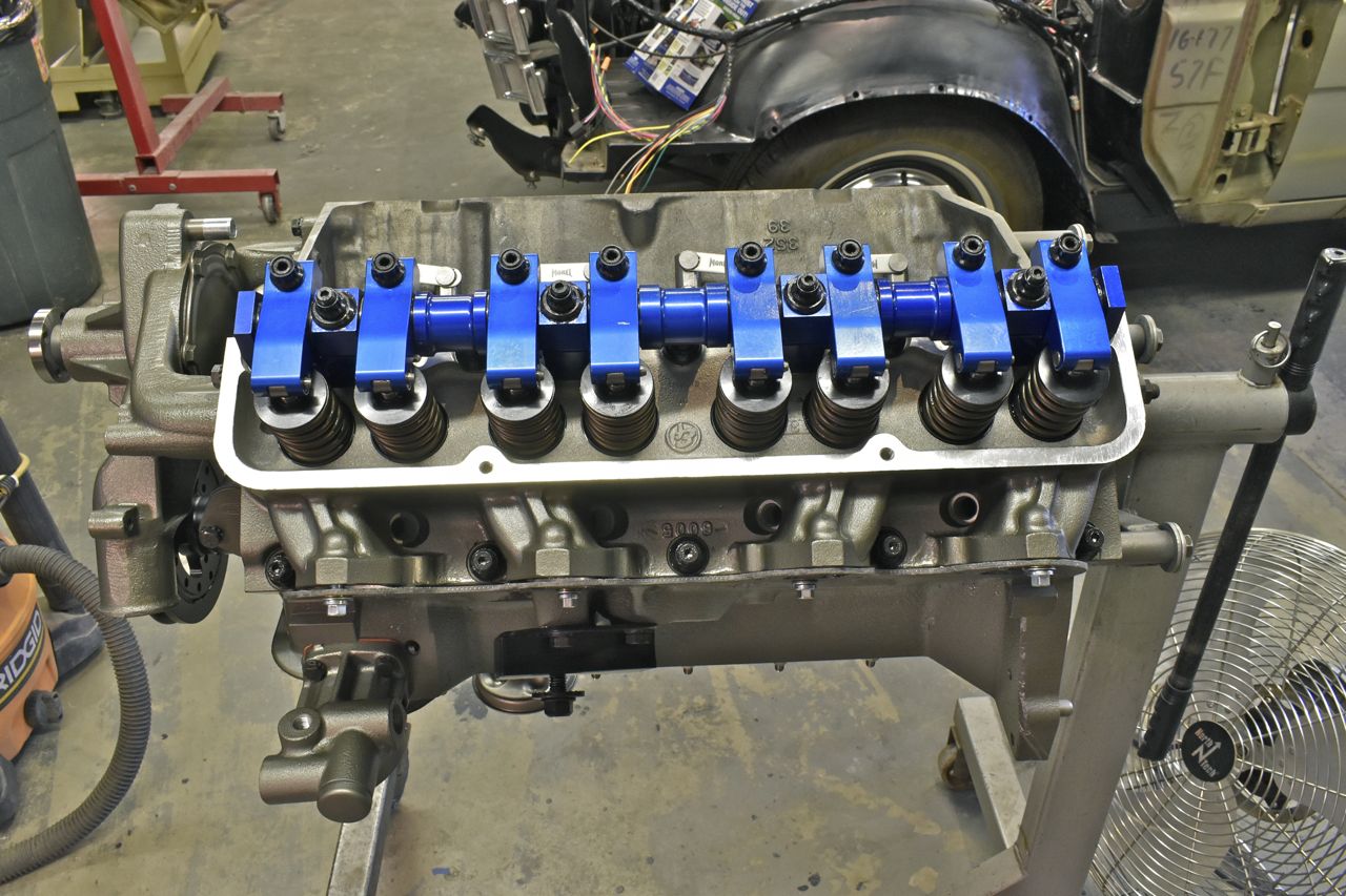
This where you play the shim game and shim all the rockers without being too loose or worse binding till they are over each respective valve stem.


It's the other Port - O - Magic head.

I spent an entire day honing, cleaning all the new valve train parts and shimming as you have to put on and take off each rocker assembly about a dozen times.
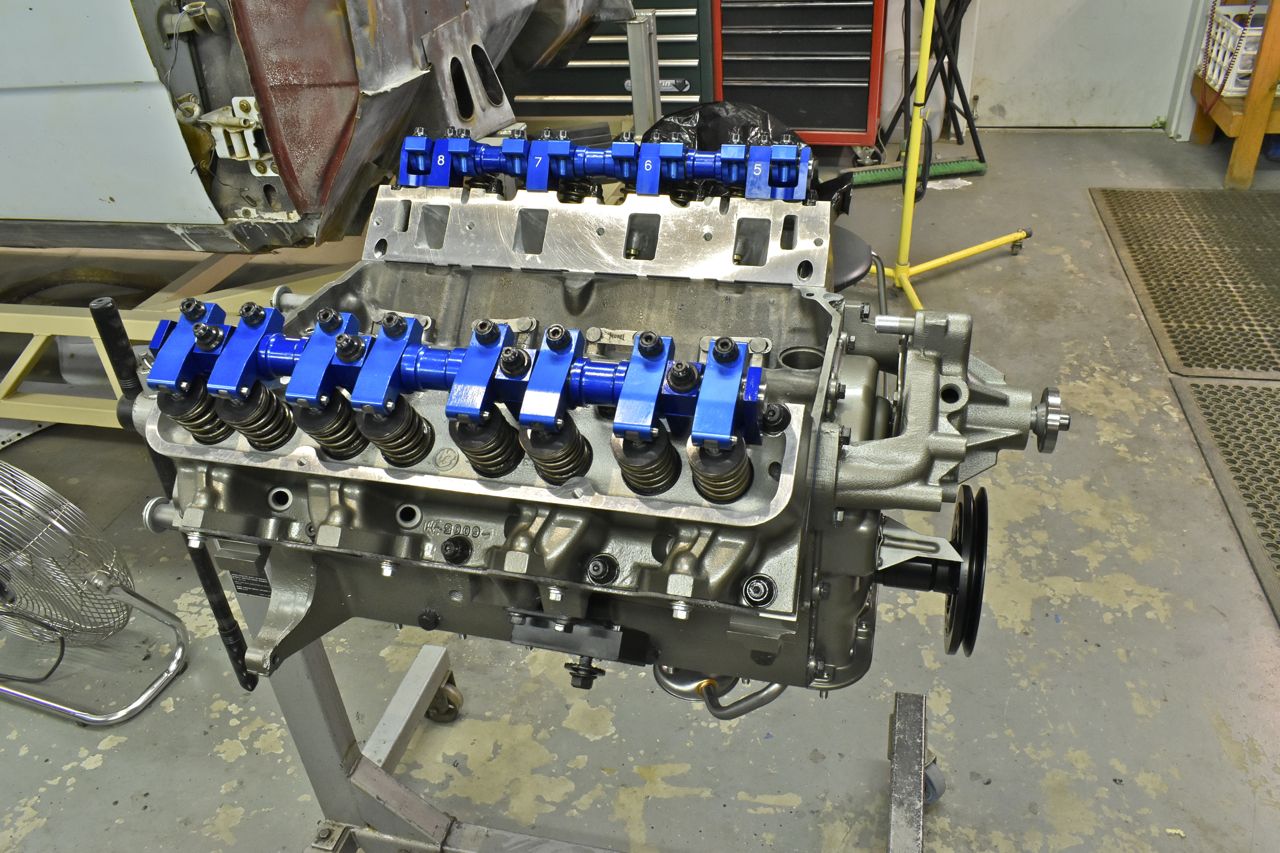
Now it's symmetrical looking.

Test fitting the manifold to see what all awaits me on what I have to do to machine this intake.

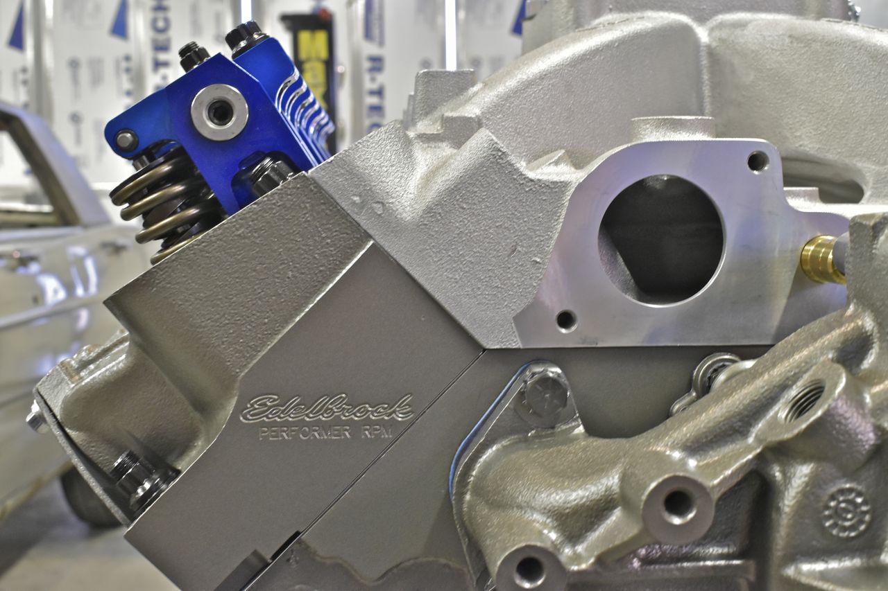
The head interface looks good. That makes me happy.

I used the distributor to locate the intake because Edelbrock doesn't believe in machining for the locating pin that's mounted in the block, withcidentally has to be removed in order to use an Edelbrock intake. So you have to use the distributor as a big locating pin.

This will have to be ground down. This is where the pad bracket bolts to the front of the engine to hold the York 210 compressor. The intake needs to be flat as the side of the head. Ironic the head and intake are made by the same company and they haven't yet figured that one out.

Oh my, it looks like Ray Charles cast this intake.

I wish I could say the other side is better......... But I can't......

More shenanigans. The bolt hole to mount the intake isn't flat, how on earth are you supposed to seal the hole from the engine oil directly underneath?????????? I'll have to figure out a way to machine the bolt lands flat.
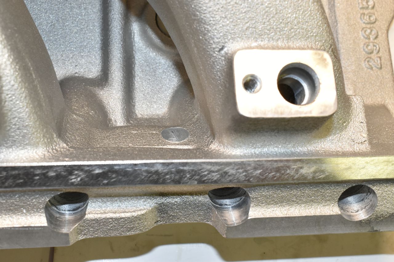
This is how it would look. This is a pretty poor show.
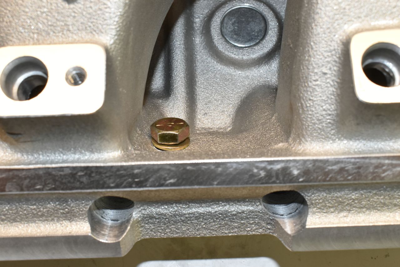
I have my work cut out for me, literally.
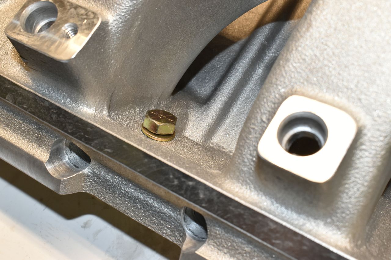
Note 1: The oil pressurize feeds to the heads are blocked off as I'm using push rod oiling since the lifters are capable and custom length pushrods are needed anyway.
Note 2: (Edelbrock we are talking about YOU) One would think that for an engine that debuted in 1958 they would have the parts dialed in by now. (laughing manically)
I noticed the bypass nipples, I'm using silicon heater hose so it's quite flexible and hoping it does the job. That intake, injectors, rails (that don't have the right hardware thank you again Edelbrock) and throttle body were 1800 dollars, the Holley components are superior compared to the Edelbrock.
Lately I am convinced that Edelbrock is the Walmart of aftermarket performance.
(sigh)
Cheers
Click here to continue to part 44