1966 Ford Galaxie 500 XL Refurbishment : 049 Engine - Fittings, Ignition Wires, Pulleys
2023, November 14
1 - 2 - 3 - 4 - 5 - 6 - 7 - 8 - 9 - 10 - 11 - 12 - 13 - 14 - 15 - 16 - 17 - 18 - 19 - 20 - 21 - 22 - 23 - 24 - 25 - 26 - 27 - 28 - 29 - 30 - 31 - 32 - 33 - 34 - 35 - 36 - 37 - 38 - 39 - 40 - 41 - 42 - 43 - 44 - 45 - 46 - 47 - 48 - 49 - 50 - 51 - 52 - 53 - 54 - 55 - 56 - 57 - 58 - 59 - 60 - 61 - 62 - 63 - 64 - 65 - 66 - 67 - 68 - 69 - 70 - 71 - 72 - 73 - 74 - 75 - 76 - 77 - 78 - 79 - 80 - 81 - 82 - 83 - 84 - 85 - 86 - 87 - 88 - 89 - 90 - 91 - 92 - 93 - 94 - 95 - 96 - 97 - 98More Engine Parts
Hello All,
I apologize if it seems like I'm all over the place. The truth is I am. There's so much to do to get right in retrofitting this old FE, sometimes one part of the process stalls on waiting on parts or indeed waiting on me.
I'm basically playing FE integration engineer for a 50+ year old car. The one man band plays a slower tune.
But here's some more progress
This was a win, well sort of. These debuted for 1968 on Fords and are just what I needed for the '66's. Now on the '66 LTD I hit the jackpot at the junkyard as there was an FE with '68 rocker covers and two of these on there. I can't use '65-'66 FE rocker covers because they will hit the roller rockers. The factory '68 covers are taller so that works out. You wouldn't believe how much now-a-days a set of used beat up steel '68 FE rocker covers go for. Holy crap. Anyway even with the old oil separators I had to carefully undue the steel lip holding the cans together, take out the steel mesh that was disintegrating, remake that out of stainless steel scrub mesh you get at the grocery store, then metal work the can shut and powder coat. So when I saw Scott Drake repopping these for 30 bucks each, well now, that seemed like quite the bargain. Although the paint job on these isn't all that and a bag of chips. I think I did a much better job rebuilding the original ones. But this still saves 4 solid hours of work.

I felt almost euphoric opening a package, removing a part and placing directly on the engine without a lengthy intervention. And that is just sad.
But back to the crappy reality and having to make my own parts. As you can see I had to drill the bottom of the new fitting to insert the stainless thin wall tubing. The rotted old heater hose fitting is above and of course there are repops but not in the size I need. Either the heater hose diameter is wrong or the pipe thread size is wrong, or both are wrong. GGGRrrrrrr

Again Ford being a pain in the.... well you know. So for the 3rd gen full size Ford with factory air con, Ford magically decided to use two different heater cores. One with same size heater hoses and one for mixed size heater hose.
Why? I have no bloody idea.
Some of the Fords we have were mixed and some were the same. That heater hose fitting depends on which heater core you have. There is no other physical difference in the heater core and are interchangeable. So to keep things simple I've bought all the same size size heater hose heater cores for all the cars already. I've noticed the brass and copper heater cores slowly disappearing, so I've already bought everything needed for the complete HVAC system for this '66 gal 500 XL and the '68 XL future project. Plus in keeping all the heater hose the same size I can just buy one big roll of silicon heater hose and just keep it all simple.

Before when I made this fitting for the '66 LTD. I had to TIG the thin wall stainless tubing to the chunky steel fitting. I can tell you that's no easy feat as stainless does not transfer heat well, but steel does. The fitting is much thicker and requires a high current setting. You have to focus the puddle of molten metal on the fitting and wash it up just long enough onto the stainless tube where you can see it melt in and then move back down and over on the fitting. 1/4 of a second too long on the stainless tube and you burn through it. In other words you really have to be on your welding 'A' game to pull that off.
I wanted to find an less intensive way to fuse the metals together and one that doesn't require concentration of a brain surgeon. Regular solder and flux will not work on stainless. So I found this. Silver solder and really nasty acid flux specifically designed to join stainless to itself or to steel.
It worked really well. It's toxic as toxic gets but worked easy and well.
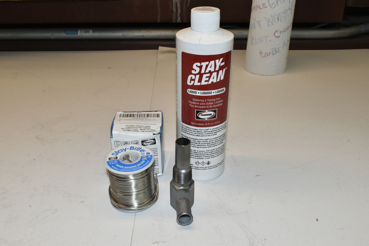
I could have used a little more flux but there's enough adhesion to the stainless for this application. The flux is just pure battery acid (sulfuric acid) with some other chemicals tossed in to enhance the toxic experience when heated.
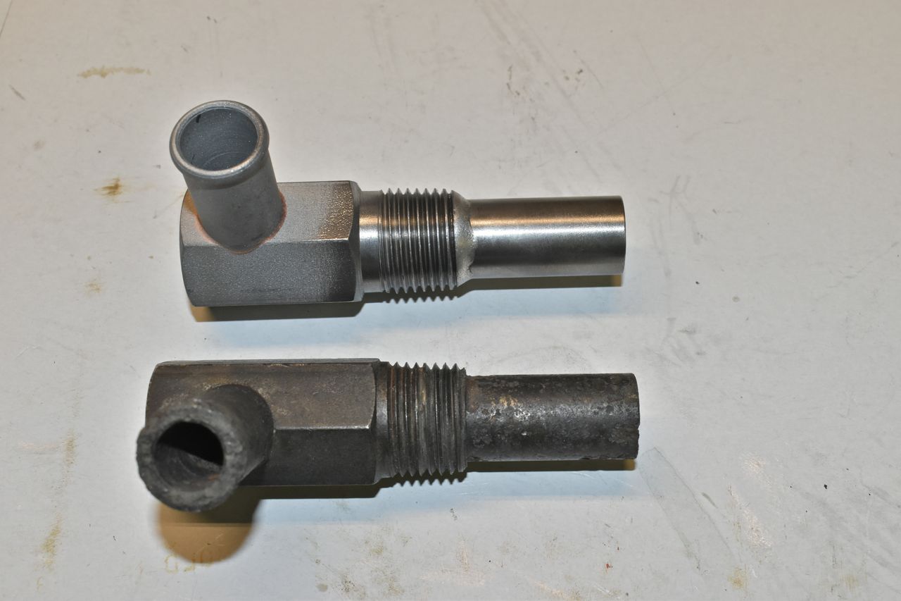
Blackened, clear coated and cured.

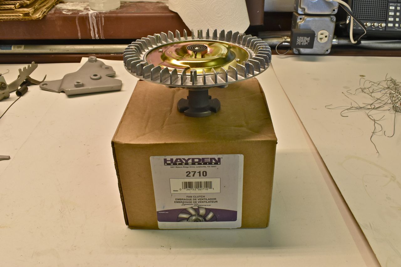
Brand new Mr. Fan Clutch.
Here's an experiment for now. So in the interim I'm still going ahead with the Duraspark II dizzy. But I need to find a more clever way to ID #1 cylinder. So I bought these pole wheels from Rock Auto to experiment on. They look to be made from powdered metal and I needed to see if I can braze to them. That part worked, braze melts and sticks well to these. So I need to cut off two poles off of one and fatten up the #1 pole only on the opposite of the triggering side. That should provide me with a lower amplitude but wider pulse for #1.
I said should, we'll see if the thickness vs the math of max rate of change of engine angular velocity works out vs signal integrity. This is still in the works.

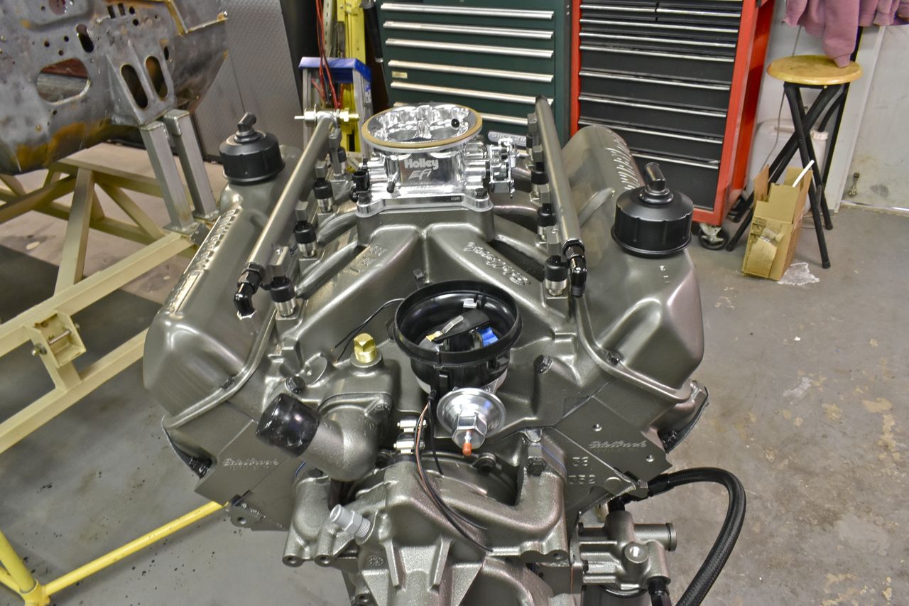
I made the stainless fuel lines to connect the front of the fuel rails together to the 90˚ elbow and also attached the fuel pressure sensor there as well. I still have to make a support bracket off the front bolts of the throttle body and have it connect to the adel clamp to support the lines and fuel pressure transducer.

carrying on....
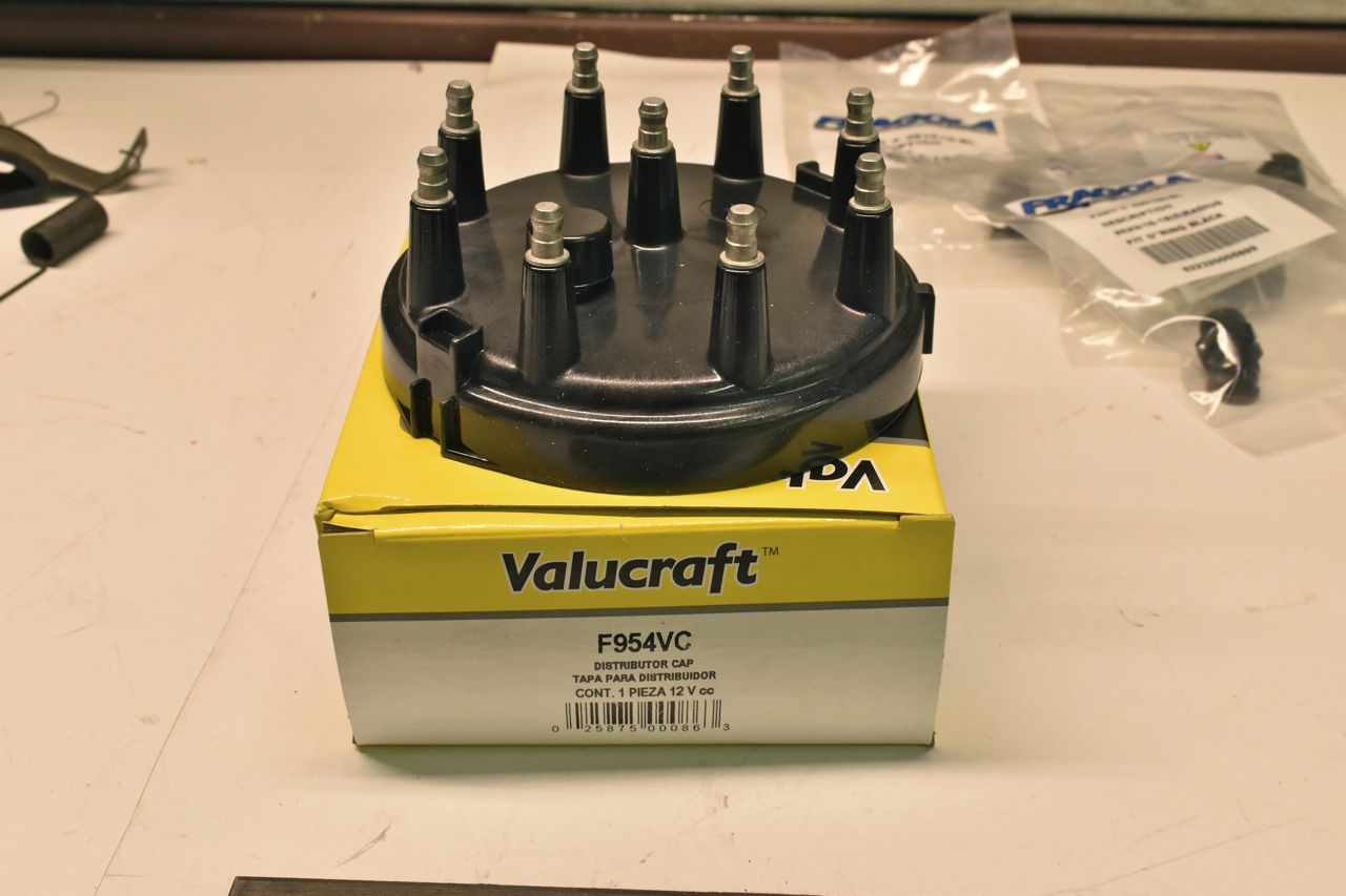
New rotor for the wide cap adapter (reduces the chance for spark scatter). Also is a GM 1 bar MAP sensor and pigtail that will mount behind the throttle body.

It's hard to find a black cap for this. They all seem to be in gray. I know I'm just picky but I've come thus far already.
For ignition wires I just went with a '77 T-Bird with a 400.


I think they'll work. I ordered wire holders for the rockers and generic organizers.
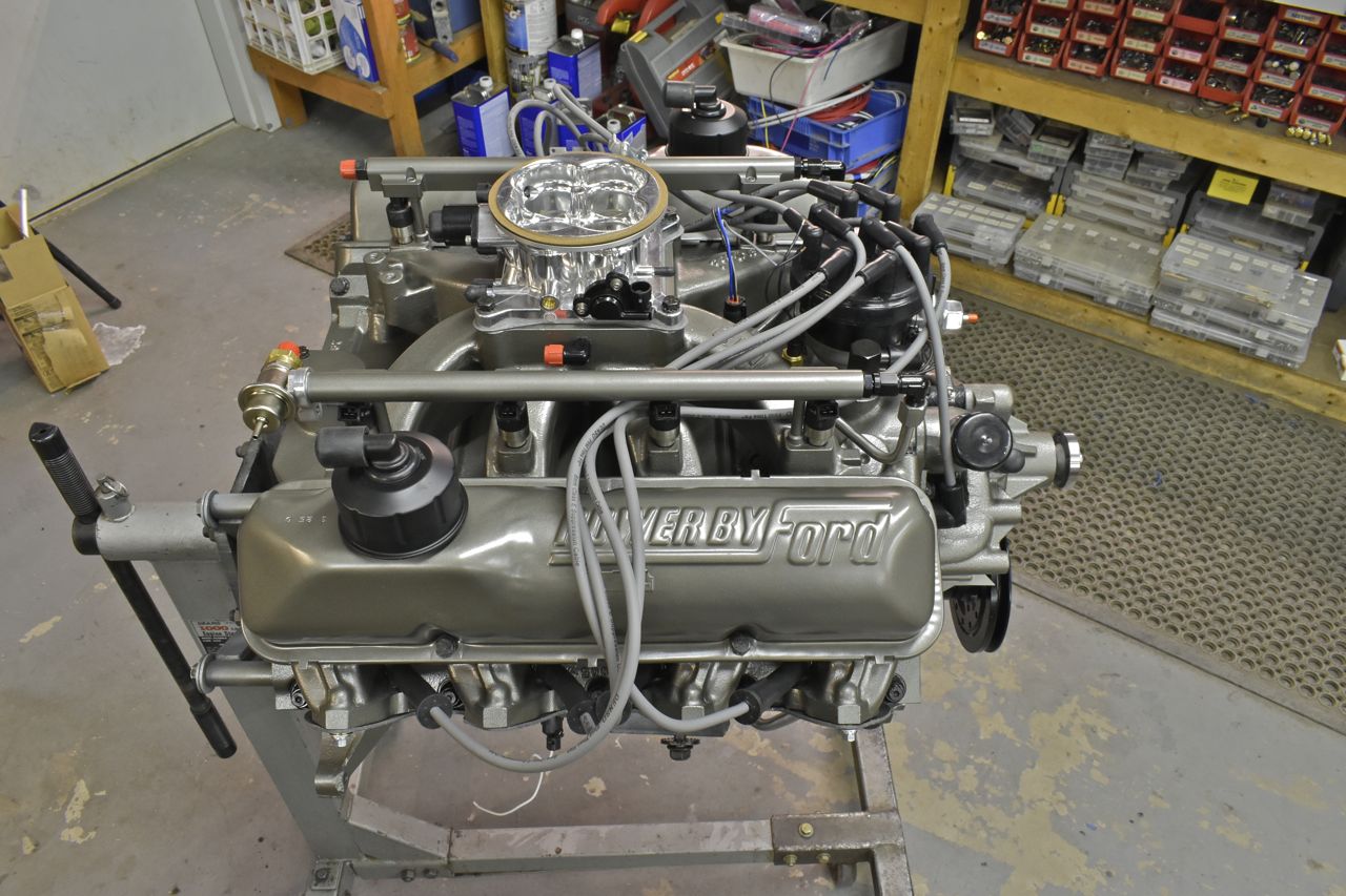
The ignition coil needs a new home as 2 injectors and a fuel rail occupy its old space. I think above the alternator and behind the big accessory plate would work. With that I need to prep and assemble those parts.

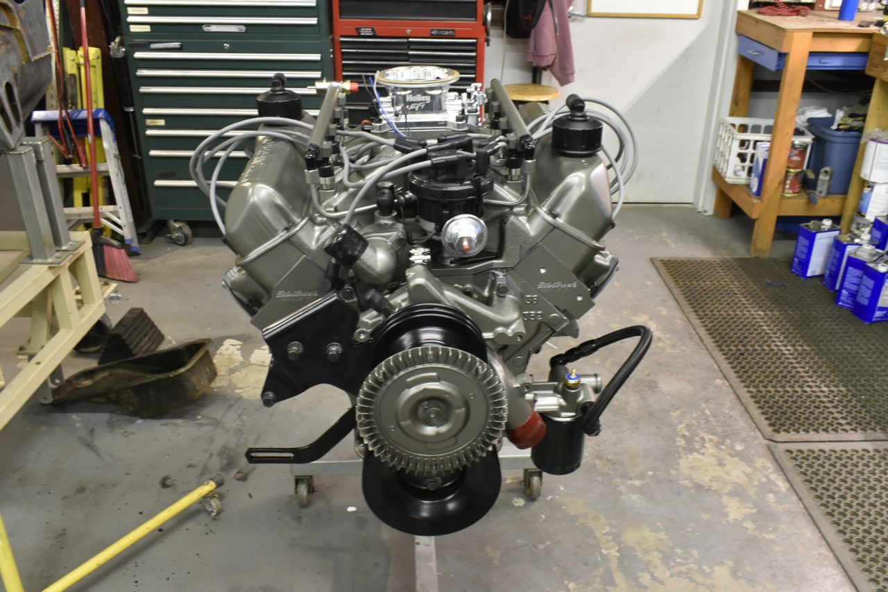

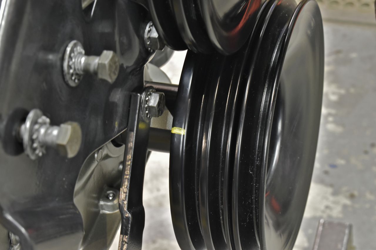
Now this is an oddity that's driving me crazy. The timing cover timing pointer resides in between the single pulley harmonic damper and the outer accessory pulley. If I flip the pointer around it's well above the accessory pulley and kind of in outer space. The other odd thing is that it points right on at 0˚TDC on the single pulley underneath but is several degrees off on the outer pulley. ??????????
I don't get it.
I thought I was missing obvious ( I tend to do that). But when I referenced the '66 LTD's 390 its pointer is atop the outer pulley just like I thought it should be. Then after studying the pointer on the LTD it's actually different. Well what the.....
So for now I just remarked 0˚ TDC on the outer pulley until I figure out a better plan.
Since this engine has aluminum heads and aluminum is unforgiving on overheating I wanted a fail safe thermostat.

Continued in next post.
Click here to continue to part 50