1966 Ford Galaxie 500 XL Refurbishment : 098 Custom LIghted Window Switches - Design, CAD and Assembled
2023, November 14
1 - 2 - 3 - 4 - 5 - 6 - 7 - 8 - 9 - 10 - 11 - 12 - 13 - 14 - 15 - 16 - 17 - 18 - 19 - 20 - 21 - 22 - 23 - 24 - 25 - 26 - 27 - 28 - 29 - 30 - 31 - 32 - 33 - 34 - 35 - 36 - 37 - 38 - 39 - 40 - 41 - 42 - 43 - 44 - 45 - 46 - 47 - 48 - 49 - 50 - 51 - 52 - 53 - 54 - 55 - 56 - 57 - 58 - 59 - 60 - 61 - 62 - 63 - 64 - 65 - 66 - 67 - 68 - 69 - 70 - 71 - 72 - 73 - 74 - 75 - 76 - 77 - 78 - 79 - 80 - 81 - 82 - 83 - 84 - 85 - 86 - 87 - 88 - 89 - 90 - 91 - 92 - 93 - 94 - 95 - 96 - 97 - 98With that I just decided to go with a good set of reproduction GM power window switches that fit 71-79 GM's. They are actually pretty well made and are solid die cast with chrome plating. I decided to take it one step further and actually back light them for that extra touch. To the best of my knowledge this has never been done before.
The idea is the GM switches have a translucent back to them where the socket slides over the pins, if I can light up the socket brightly, then it will shine through the switch and reflect off all the front chrome surfaces, it should provide an interesting look.
I'll need to reproduce the socket in a translucent nylon and then design a small PCB that mounts atop the socket back that has bright LED's that can shine through. A while back I completed the single power window switch lighted socket, all I needed to do was finish the dual and quad GM power window switch sockets. Let's see how it all turned out.

These are older pictures showing the progression of making the lighted socket from scratch. There's a top and bottom nylon piece for the socket. The socket must house the original GM Packard type terminals and wires. So this is the idea. Then a PCB must be made that will fit into the top nylon section and the whole thing can be screwed together.

Here's the boards I designed and had a board house make.
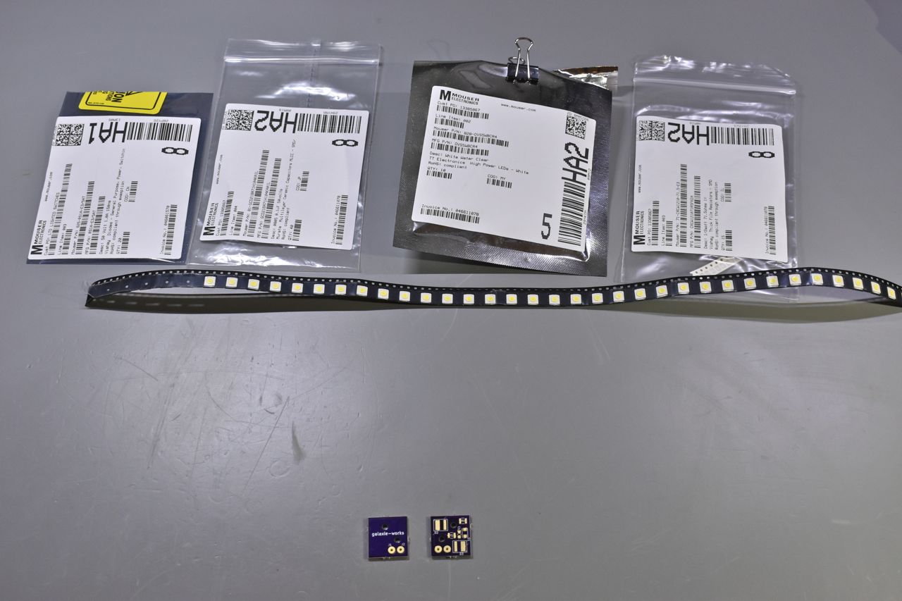
Once the boards arrive it's time to assemble them.
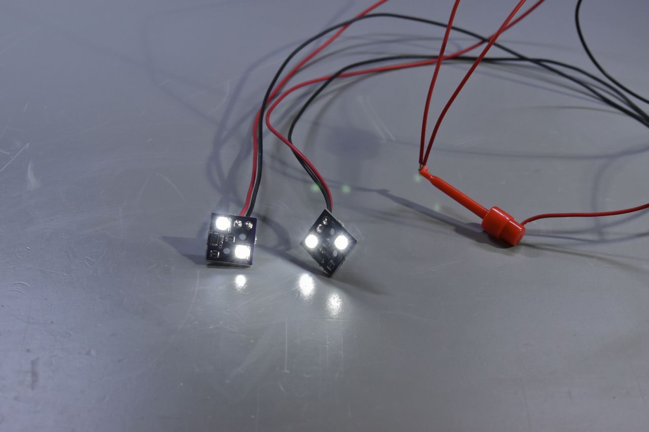
There's the lighting portion of the switches.
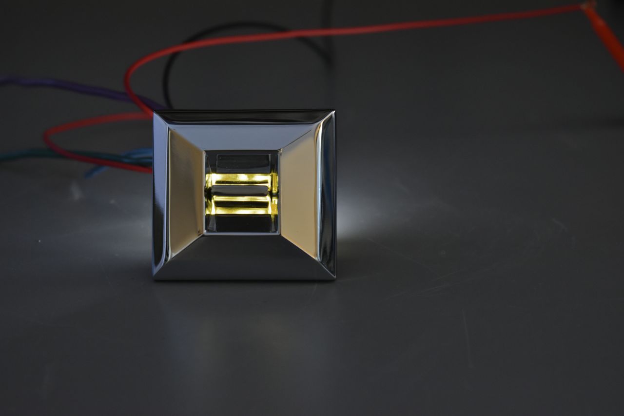
This is the effect with the socket installed behind the GM single power window switch. It looks rather classy like this.
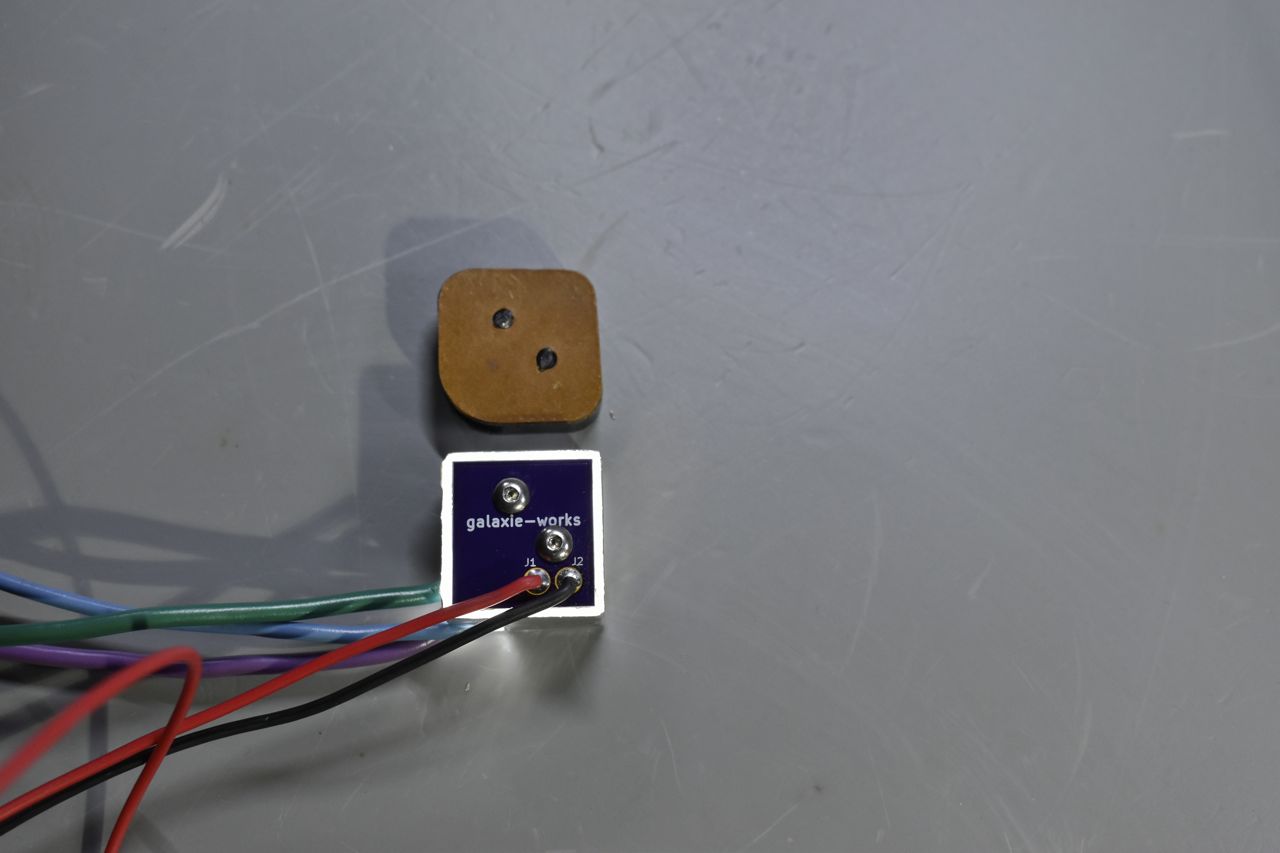
Here's a comparison of the original GM socket (above) and my lighted socket.
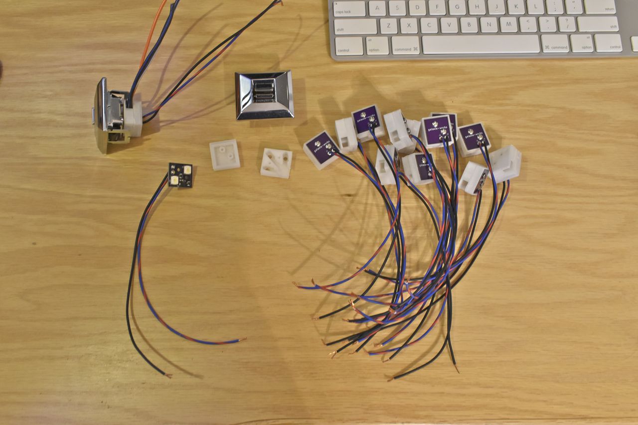
I had a lot to make of the single switch sockets.
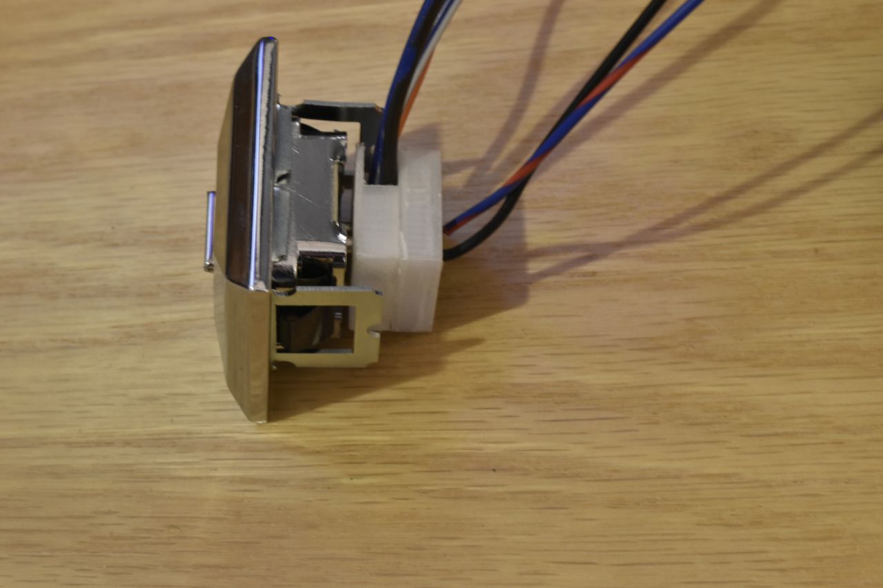
This is the back side fitment.
That was done a while back and I just finished the dual and quad sockets. I figured I'd show more of the process for those interested. The following with be the quad lighted socket (the most complicated).

The first thing I had to do was design and print out the socket assemblies for the dual and quad GM switches.
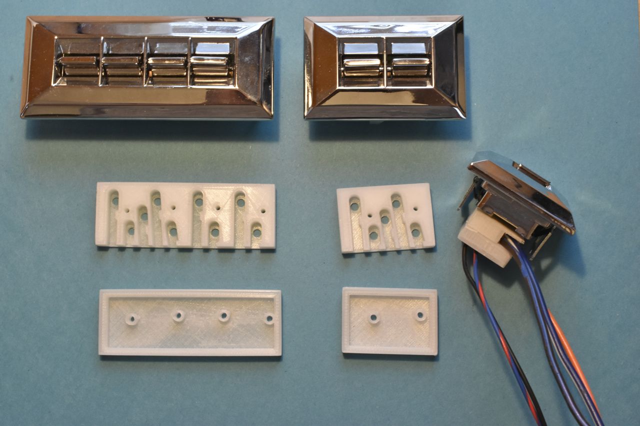
These represent the types of switches used. Next is to design the lighting PCB for these. I'll just show the Quad as an example.
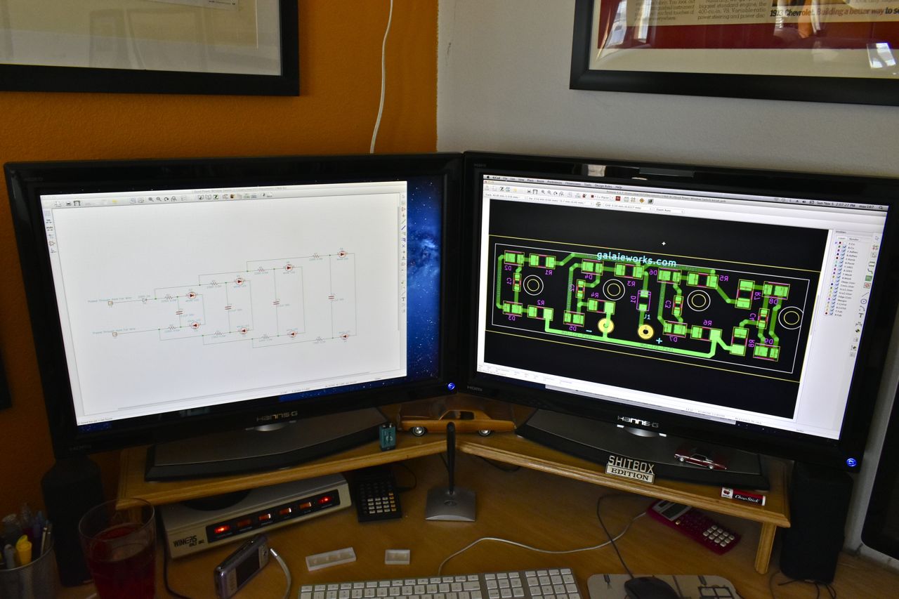
This is the schematic and board layout programs. Having dual large monitors makes it so much easier. I am using Kicad, which is a free program for doing such work. For freeware it's pretty advanced and more than suitable for this. I am pretty use to its idiosyncrasies and can work around its shortfalls.
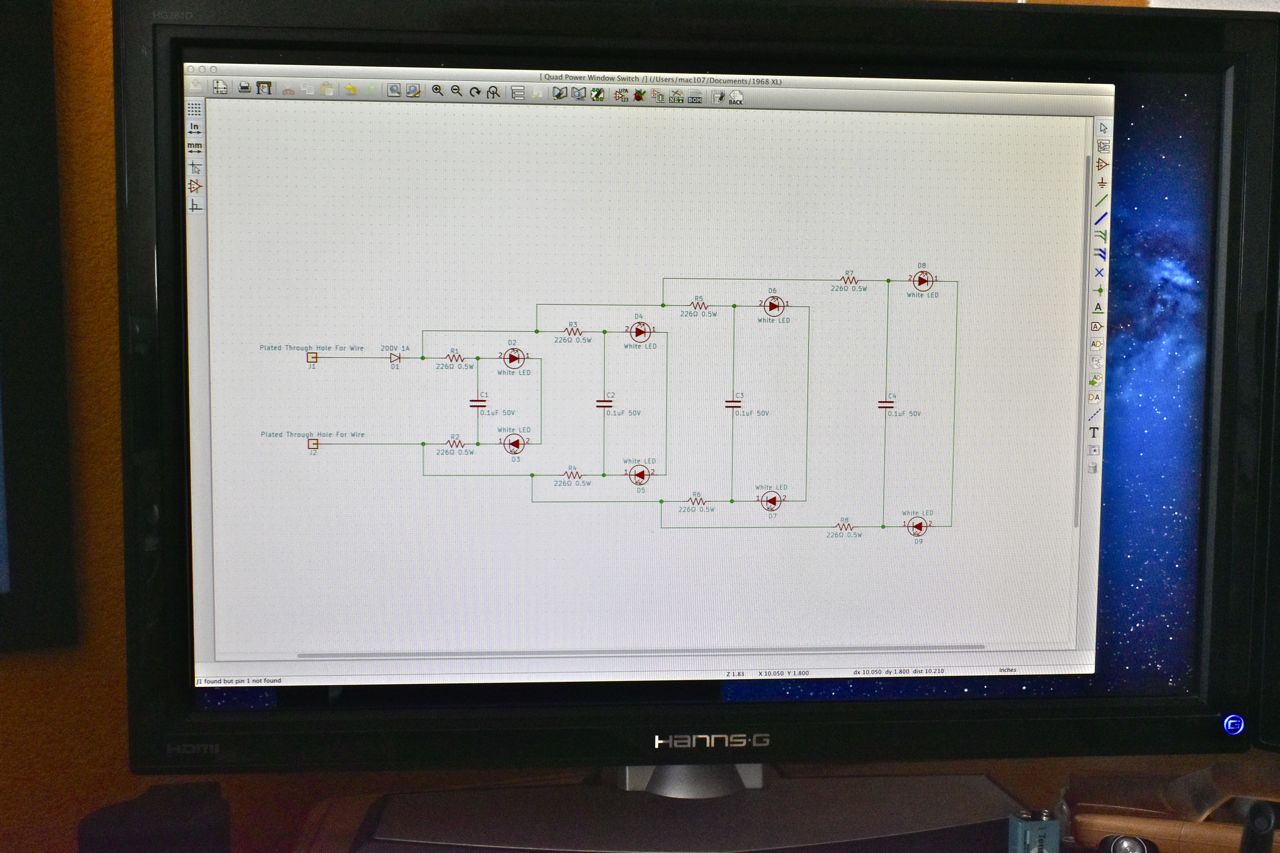
For those interested in the design, there's many facets in just a simple lighting circuit for automotive use. First and foremost is the reverse polarity protection diode on the input. This protects up to -200 volts on the vehicles wiring. Brief pulses (~50 ms) up to this magnitude can exist when switching high inductive loads on and off (think blower motor or power windows or locks or an electric cooling fan). Most of that will be inductively coupled from adjacent wires carrying that current. The capacitors across each grouping of LED's is there for ESD protection. It will downgrade significantly any static electricity from rising to quickly and too high. Those are just there to protect the LED's from handling the board or wiring harness. Splitting up the resistances also helps with ESD and the only reason why two resistors per group is used instead of one.
To handle the colloquial term "load dump", the simple solution was to use high powered LED's and only run them at a very small fraction of there total power. This will allow a +200 volt pulse to be handled with little problem. "Load dump" is simply when the alternator is powering high loads (such as charging a discharged battery) and you suddenly disconnect that high load. The alternator cannot shut off instantly and what happens is the current continues to flow and if the high load is gone, this causes the voltage to rise very rapidly but only for a short duration (typical 1-400ms). The LED's will simply get really bright but not incur any damage as a result.
If you were to simply run a single resistor with just two LED's in a grouping and tie that to the vehicles system all the while picking LED's that were running >85% of rated power, they would not live a long life in an automotive environment with daily use. Understanding the harsh electrical noises and pulses that occur in a vehicles electrical system is key to designing electronics that live a long time in such an environment.
SAE testing documents have all that information and recommended testing for those conditions in any new product.

The board layout shown above is rather straightforward once the schematic and part selection is ironed out. Since I mechanically designed the sockets I have the DXF information regarding the board outline as well as keep out areas. Those are imported first and then placing the components and traces can commence. There's a couple things to keep in mind, for example when determining the board outline I shrank the edges inward 0.005" on each side so the the PCB's will fit nicely and to allow for variation and manufacturing tolerances. The Printed Circuit Board house you choose should have its limits published and this can help you decide how much wiggle room you need.
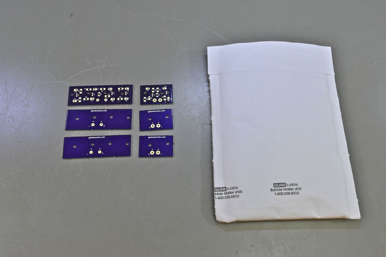
I use OshPark to make the boards. All you have to do is send them the files from the program you used to make the board and a credit card. In this case it was 22 dollars for these 6 boards. Those included 3 of the quad switch boards and 3 of the dual switch boards. It took about a week and a half to get in the mail. They are double sided.
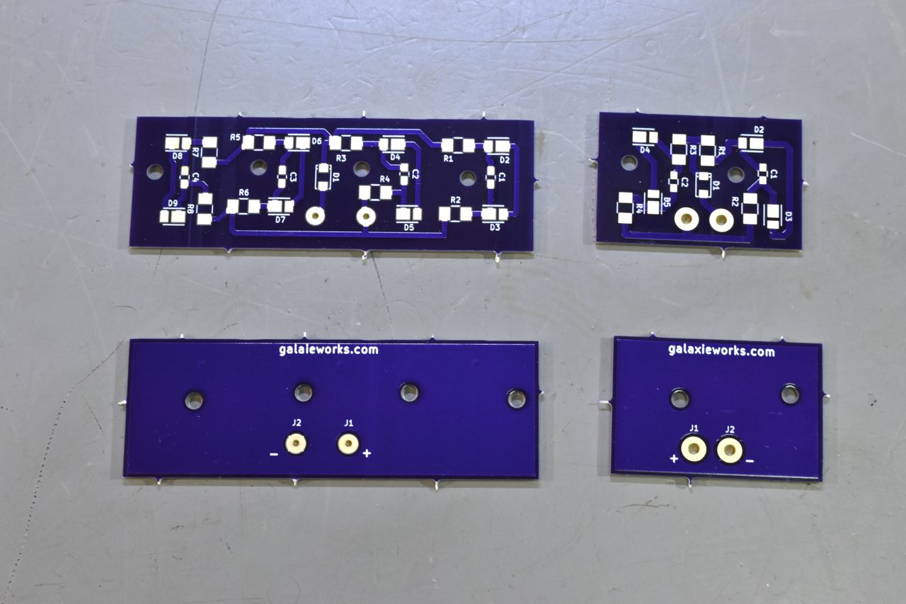
I did make one mistake that is glaringly obvious. I thought I chose the same vias for the wire connections, but alas I did not. I was working on both boards at the same time. Sometimes mistakes are made, especially if it's just you doing the whole thing from start to finish. It's no big deal, though, in this case just a little more solder will take care of this.

Assembly time, it's important to be clean and organized.
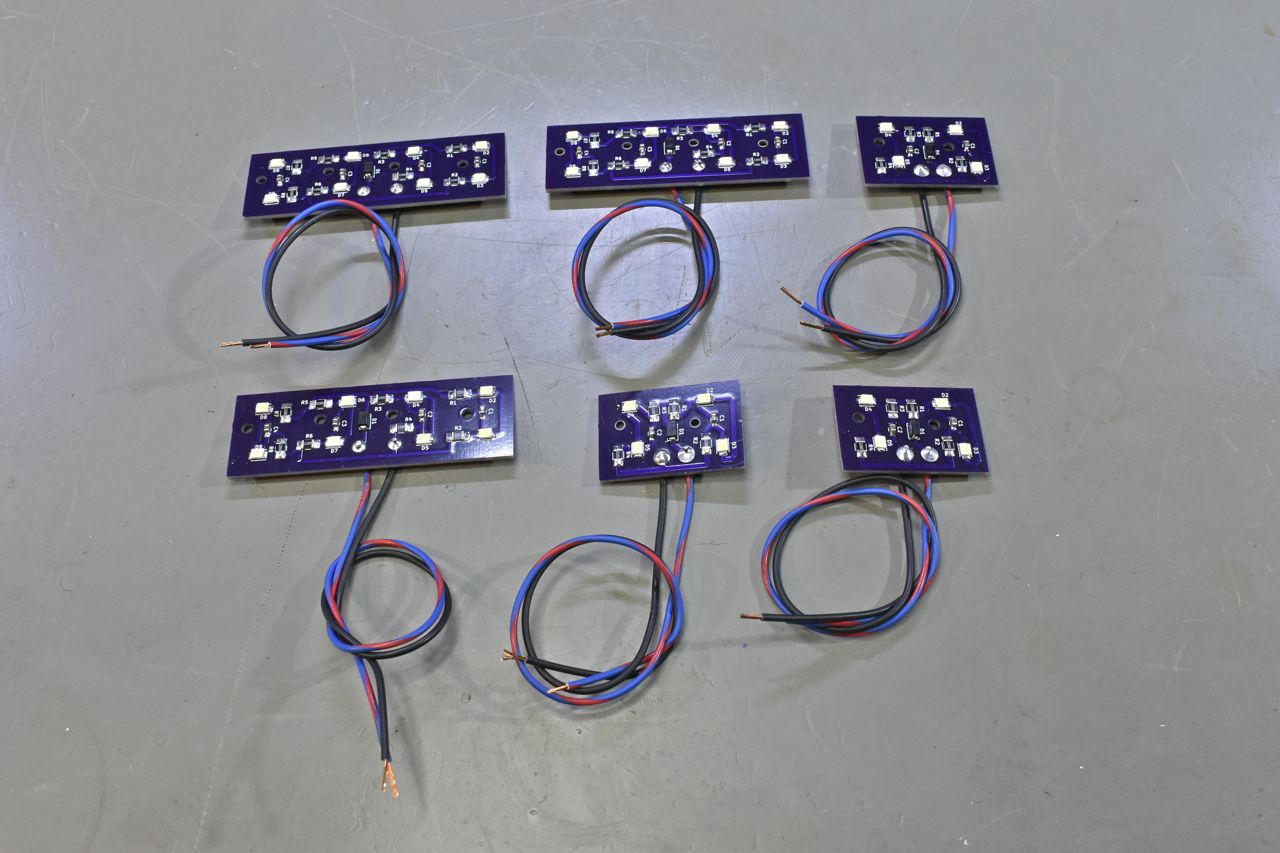
Everything is of course hand soldered. If you were going to do a low production run of say 50 - 100 you would specify glue dot and if the board house will allow and ship carefully; solder paste in the board files. Then you can manually place or use an auto populator machine and reflow the boards. It would still be a manual operation to solder the wires unless all the components can handle a wave solder process.
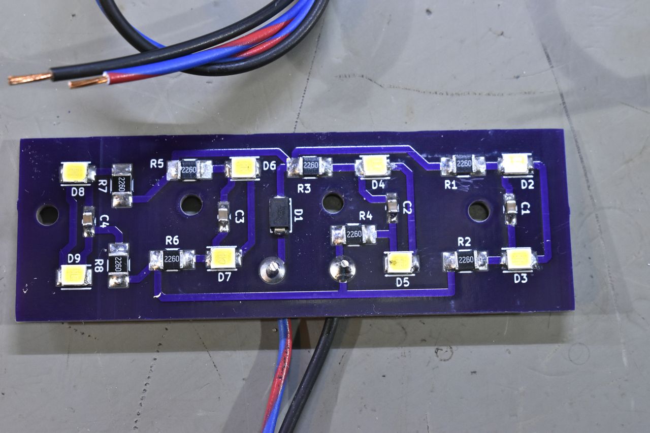
Not to bad to do. Those LED's can be tricky though.

And the dual switch lighted boards completed.

To check them out I brought out the different styles of the switches I would be using. I have some singles, duals and quads all with the lighted sockets attached.
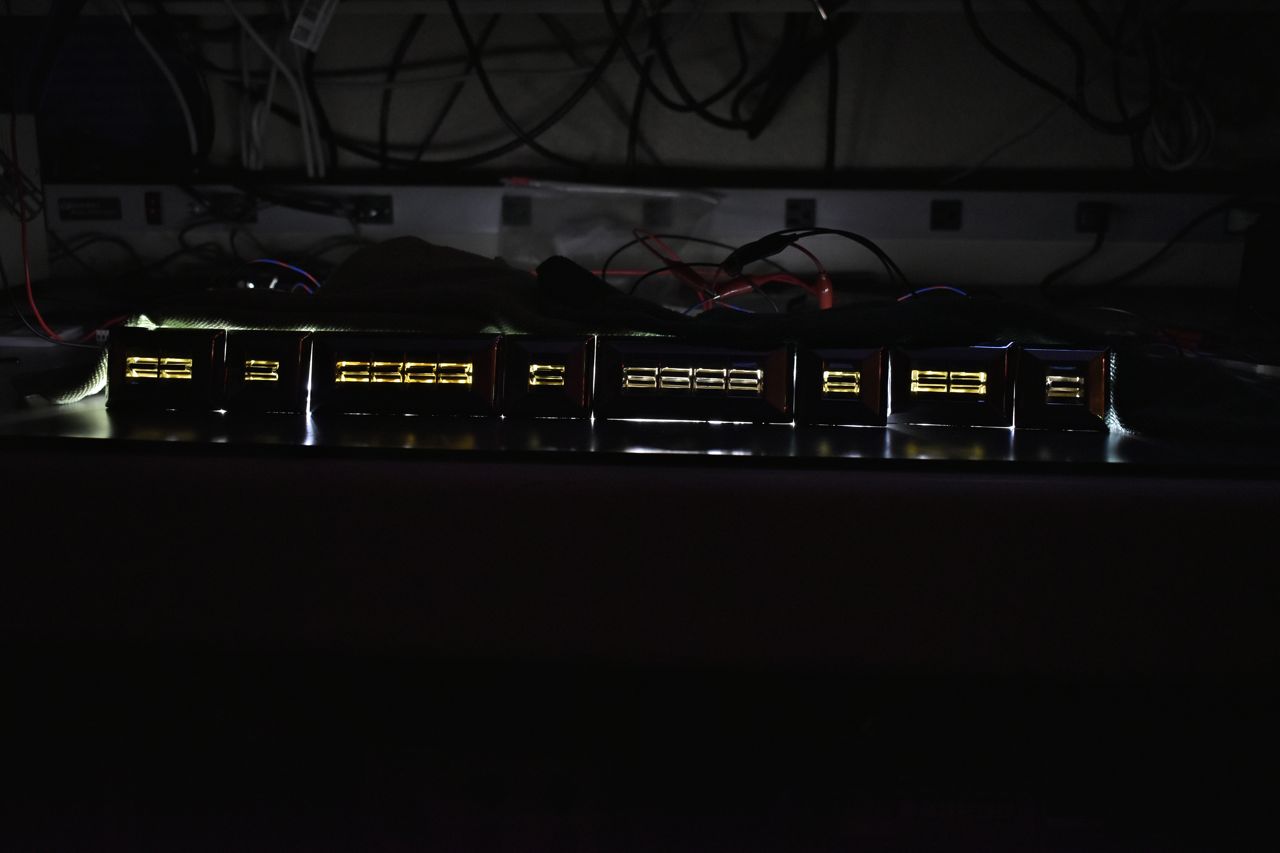
I'm happy with the outcome. These will look very nice installed in the cars.
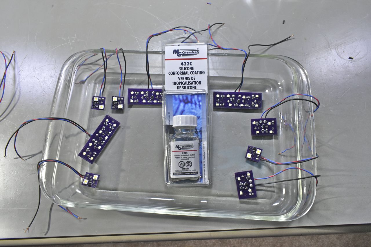
One last step. I've seen many aftermarket kits like; Cruise Control (Dakota Digital) and the Carb Cheater to name a few and others that should really have this step and did not. This will seal the board against moisture and subsequently corrosion which can cause all kinds of problems and malfunctions. All the OEM's use this. It comes in two flavors, either a soft rubbery variation or a hard like paint variation. This is the hard like paint variation.
Since these boards are inside the door where it will be wet at times (rain, snow, car wash) it's important to protect the PCB's and components.
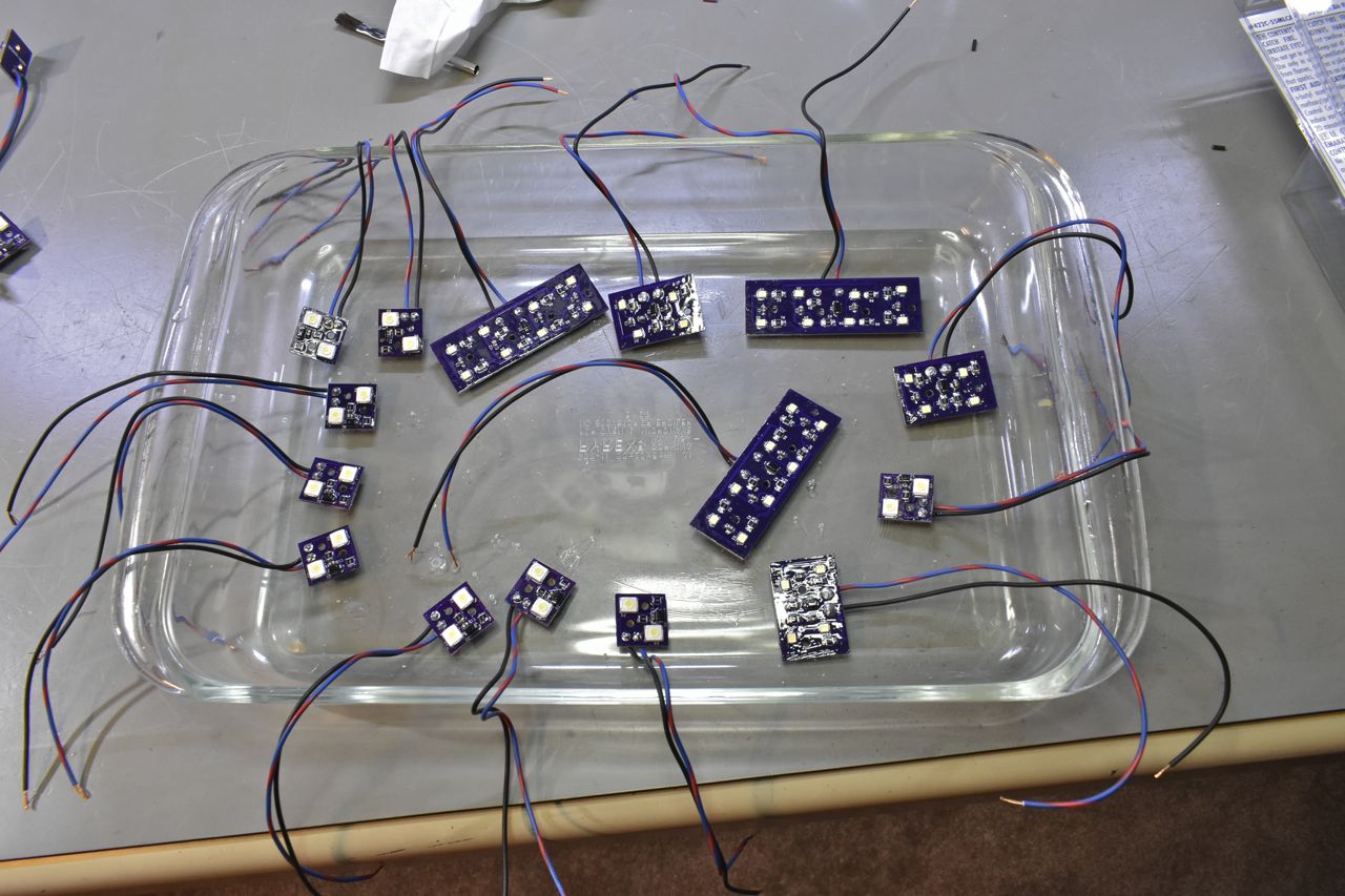
Since this is a low run I elected to just use the little brush and just paint it on. In higher volumes you can dip them or have them sprayed on.
And that's that for the power window switches and back lit sockets. Now as far as electrical connections are concerned there is a problem using the GM power window switches with the Ford full size power window motors. They are not suited for simple connections because the GM switches are for dual wound series motors and the Ford full size motors are just ordinary permanent magnet motors. So what does all this mean. Well in a nut shell you will need 2 standard 5 pin Bosch style relays per window motor to mate the GM switches to the Ford full size motors.
Now why do I emphasize "Ford full size" models? Well it appears the T-Birds of the mid to late 60's also used a dual wound field window lift motor just as GM did. Why did Ford use two different classes of motor for the power windows on their cars?……. You got me…….. That is some corporate and or marketing shenanigans I'm sure.
So what's the difference between the two motors; dual wound field and permanent magnet? Well the dual wound field window motors simplify wiring and those motors produce a lot more torque (think electric drill motor) but are more expensive to manufacture. The permanent magnet motors are less expensive to manufacture, but have less torque, so the windows might be slower in cold weather or snow packed weather, or with heavy icing, they might not move at all. The dual wound series motors would just break all that and either put the window up or down regardless of conditions and with force. Whilst I can't speak for the Ford dual wound field motors I can speak for the GM dual wound field motors. Lets just say that if you were foolish enough to put your wrist in between the glass and the metal body of the car and hit the up button the Ford permanent motors would stall and just probably lightly bruise your wrist. The old GM windows would heavily bruise or break your wrist. GM used those motors into the late 70's before going to permanent magnet motors in all their cars and trucks.
So how is each wired?
The dual wound field motors are simple. You ground the motor housing (B-) and apply B+ to one wire for up or the other wire for down. Easy peasy Japaneasy.
For the permanent magnet motors you would apply B+ to one wire and B- to the other wire for one direction. To change directions you have to swap B- and B+ wires to the motor. So either the switches have to be more complicated or as I mentioned you can use 2 relays per motor to control them.
As an interesting side note, when I bought the 4 regulators for the 1968 XL (1968 2 coupe/convertible) off of Fleece-Bay, err E-Bay it was mentioned that none of them worked. I thought even that's pretty rare for 4 failures. Well when they arrived, all four did in fact work. I mean they were really slow and the motors noisy, however they worked. What could have happened is that whomever removed these tested them like a T-Bird motor, of which in that case they would not work.
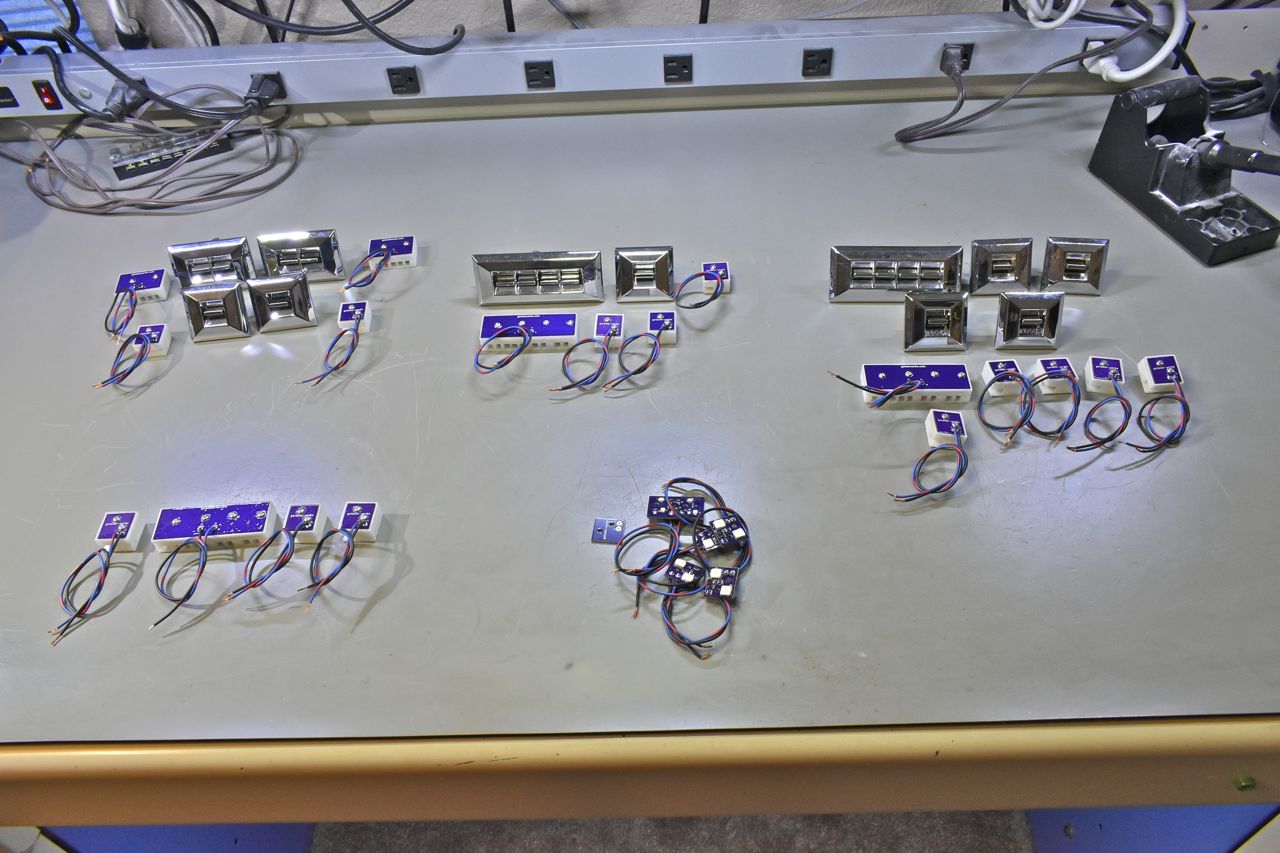
Just to better explain the above picture, the grouping of switches in the upper left is for the 1966 gal 500 XL. The dual switches will be mounted in the centre console stacked to appropriate as best as possible an original configuration. Each of the single switches will be mounted in the rear quarter cards. There will be no switches in the front doors.
The upper middle grouping of switches is for the 1966 LTD. The quad switch goes in the drivers door and the other doors receive the single window switch. Two are missing because they are already installed in the door cards.
The upper right grouping of power window and power lock switches is for my 1973 Caprice Classic convertible. Each front door gets a lock switch along with the customary power window switch. There's one missing because one power window and one switch is already installed in the car.
The lower left grouping of just sockets is for the 1968 XL. I just ordered another round of 1 quad and 3 single power window switches for that car. Just waiting for those to arrive.
The bits in the lower middle are just extras and leftovers.
Now I do plan to add power locks to all three old Fords. They will be electric locks and I'll be using another decently reproduced GM power door lock from 1977 - 1990 for those. I will not be adding the lock switch to the front doors but rather more convenience package orientated power lock switch location.
I hope you enjoyed.
Much more to come on the power windows and locks.