1966 Ford Galaxie 500 XL Refurbishment : 037 Clock
2023, November 14
1 - 2 - 3 - 4 - 5 - 6 - 7 - 8 - 9 - 10 - 11 - 12 - 13 - 14 - 15 - 16 - 17 - 18 - 19 - 20 - 21 - 22 - 23 - 24 - 25 - 26 - 27 - 28 - 29 - 30 - 31 - 32 - 33 - 34 - 35 - 36 - 37 - 38 - 39 - 40 - 41 - 42 - 43 - 44 - 45 - 46 - 47 - 48 - 49 - 50 - 51 - 52 - 53 - 54 - 55 - 56 - 57 - 58 - 59 - 60 - 61 - 62 - 63 - 64 - 65 - 66 - 67 - 68 - 69 - 70 - 71 - 72 - 73 - 74 - 75 - 76 - 77 - 78 - 79 - 80 - 81 - 82 - 83 - 84 - 85 - 86 - 87 - 88 - 89 - 90 - 91 - 92 - 93 - 94 - 95 - 96 - 97 - 98Clock
I took a bit of a sidestep and finished the clock. Sometimes you need a break and focus on some other more interesting part of the car. Clocks now-a-days seem so trivial as they are either a digital part of the radio or sat nav. But 50 years ago they were a mechanical precision instrument.
This one was dead however as most old mechanical automotive clocks ended up.
This is the clock cover and you can see, it had many many years of service as the points inside the clock arced themselves to near oblivion. Actually all this crud was all over the gear train and ironically saved the clock from further damage. Let me explain.

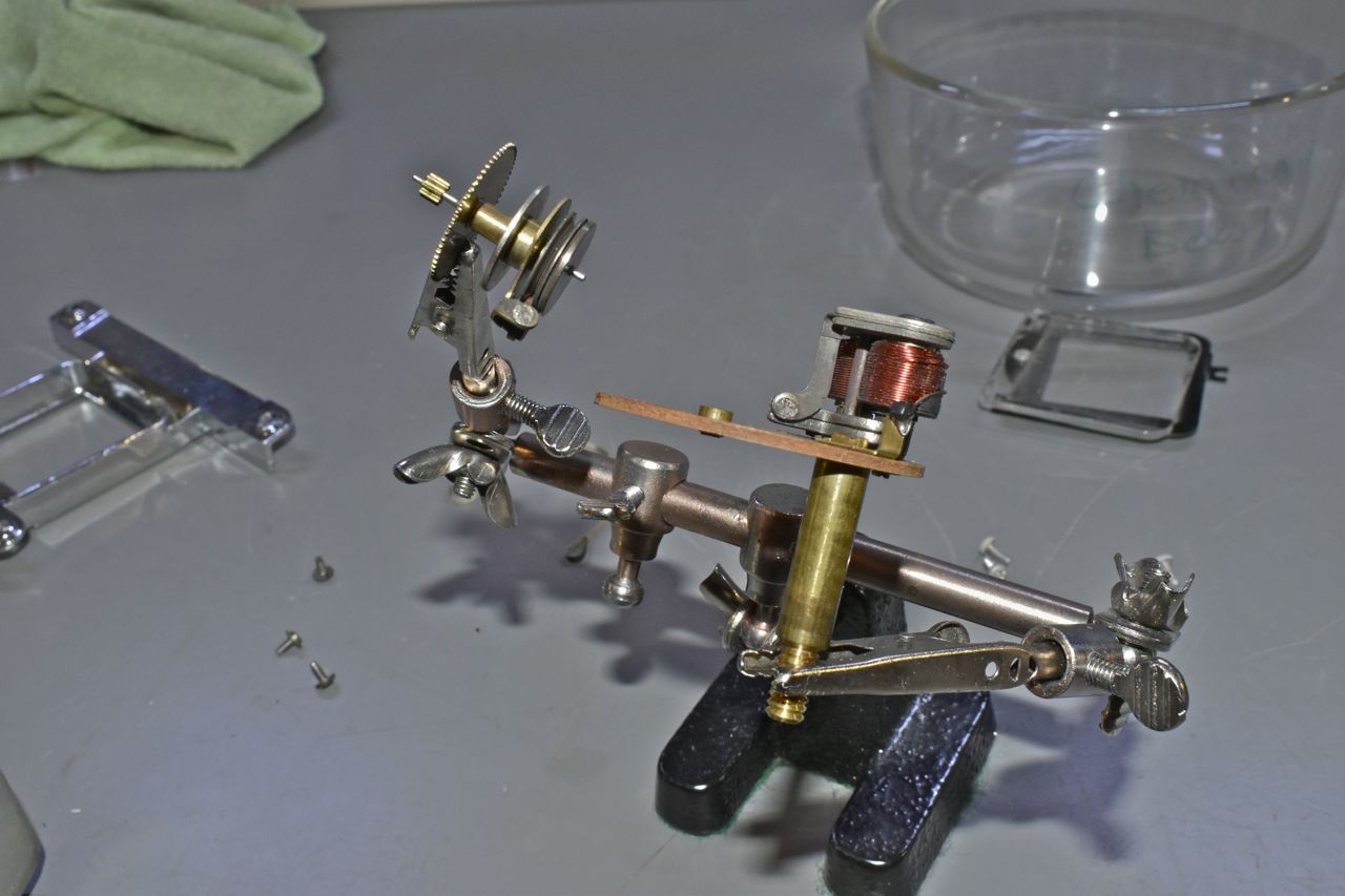
This is the gear train after I washed and lightly brushed it with lacquer thinner. The flywheel would not oscillate as it was covered in burnt bits of points. The winder, mainspring and mainspring drive gear are removed here.

You can see the points are just about worn away, that's a lot of arcing over the years. What usually happens to these old clocks is at some point in the cars long life the battery is allowed to slowly drain, either from accidentally leaving the lights on or just plain neglect. The winder is a high current intermittent device and relies on at least 9 volts to effectively whack one set of the points on a one way clutch and wind the main spring up ever so slightly. If the battery voltage falls off the winder can't slap the points hard enough and it stays engaged and the windings will burn.

The grunge on the gear train allowed one last winding and there it stayed with the winder disengaged and most likely saved it.
There were a couple of problems with this clock aside from all that. First the centre screw on the winder board must have vibrated out over the years and when I tried to separate the cover from the clock the tension snapped the board near the outside screws. I had to use a strong industrial adhesive to affix that back together. The other problem was the points are just about obliterated.
So what I've done is use a solder with a high percentage of silver in it to build the points back up and file smooth as best I could.

One of the modifications I made was to include a freewheeling or flyback diode across the coil and this greatly reduced arcing. This is a 5 amp fast recovery Schottky diode. This should greatly extend the life of the points.

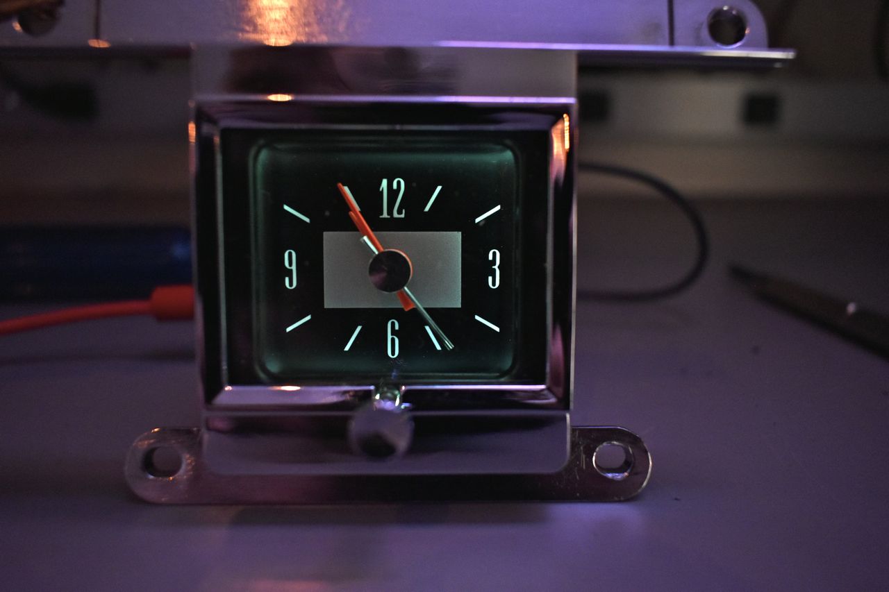
After I oiled and blew off the residual heavy oil with canned air the clock works great. Interesting tidbit about these clocks is the semi-auto adjust feature. Say the clock is too fast, every time you adjust the clock backwards to correct another gear set is activated on the initial movement that takes a bit of tension off the hair spring to slow the flywheel down, thereby slowing down the clock. It works in the opposite fashion as well. There is a slot on the side of the clock for a manual speed adjustment if you wish to time against a stopwatch, of which I did. I let it run for a week on the bench and it was on the money.

I also experimented with different light bulbs. The clock lamp is an 1816, however it's a pretty high wattage bright little bulb that generates a great deal of heat. I also noticed that the light reflects inside the rear cover and so a bright inside surface is required. Also the 1816 is a long nose bulb with its filament close to the back of the winder board. This doesn't do much good for the illumination to the front.

I experimented with a variety of different light bulbs I had on hand and discovered the 1895 (same as the dash turn signal indicators) illuminate just as bright and are lower wattage wise so lower heat. The bulb is a bit shorter and puts the filament a bit closer to the back of the clock and sheds effectively a similar amount of light forward as the long nose bulb with the benefit of less heat.
It is after all a precision instrument and not a miniature Easy Bake Oven.
I experimented with a variety of bulbs. These are both completed clocks for both '66 cars.

Tis the difference between the bulbs.

A note on what I used for this endeavor. You need a high wattage soldering gun to solder to the big brass lug, otherwise you risk cooking everything, including the diode, trying to get the solder to melt. You want to heat up quickly as possible, melt the solder then cool. To keep the diode cool I inverted the duster can and let the liquid refrigerant boil on the leads to take the heat and cool off the large peg.

The oil I used was Tri-Flow with TPFE, once I oiled it I blew off the excess from the gear train with the canned duster. The lab squeeze bottle has lacquer thinner in it for cleaning the gear train. I used the regular low wattage soldering iron to build up the points and solder the diode to the small metal post.
Next up more trials and tribulations with the engine.
Cheers
Click here to continue to part 38